This article is designed to help users understand draft angles on WAZER Pro. It will first discuss why all waterjetting leaves a draft angle and describe the basic physics at play in during a cut. It will then explore the effect of material and thickness on draft angle. A study of cut speeds impact on draft angle will follow. Key take-aways and best practices will also be discussed.
Why does waterjetting leave a draft angle?
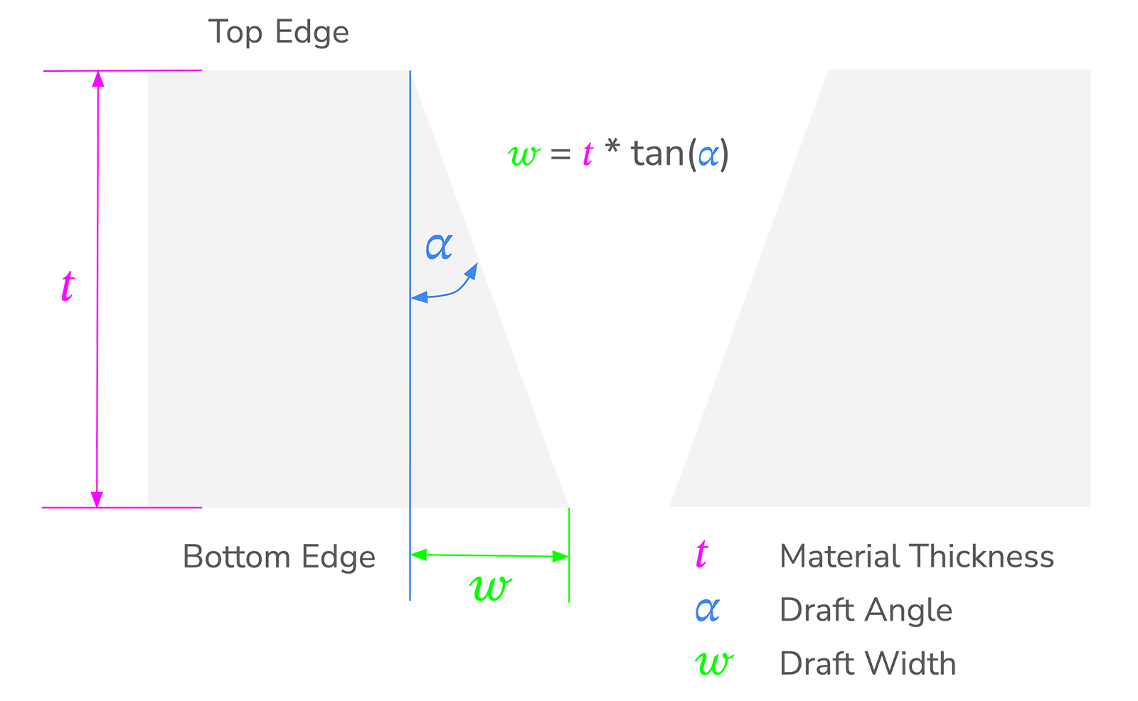
Waterjets derive their cutting power from a high-pressure slurry composed of water and abrasive. As the slurry cuts, the overall stream deflects, narrows, and slows. This causes the kerf, or the amount of material removed by a cut, to narrow across the workpiece’s thickness (𝑡). The difference in width between the bottom and top edges of the workpiece is called the draft width (𝓌). The angle created by this difference is called the draft angle draft angle (𝛼). These quantities are illustrated in the figure below.
When cutting with WAZER Pro, draft angle will be driven by two main factors.
- Material Thickness
- Cut Speed
This article will help explain the impacts of these two factors on draft angle for parts cut using WAZER Pro. It is important to keep in mind that draft width (𝓌) is a function of draft angle (𝛼) and material thickness (𝑡).
𝓌 = 𝑡 * tan(𝛼)
Material thickness (𝑡) will always have a larger impact on draft width (𝓌) than draft angle (𝛼). This is entirely due to the geometry described in the formula above.
How Does Material and Thickness Affect Draft Angle with WAZER Pro?
To help quantify draft angle’s variability across material thickness, our team performed a series of test cuts on 4 commonly used materials:
- 6061 Aluminum
- 304 Stainless Steel
- A463 Low Carbon Steel
- High Density Polyethylene (HDPE)
Each material was tested at a range of thicknesses. For each thickness, 4 test cuts were performed and 8 draft angle measurements were recorded. These cuts were performed at the speeds listed on our Materials Specs page. For a full test procedure, please refer to the appendix of this document.
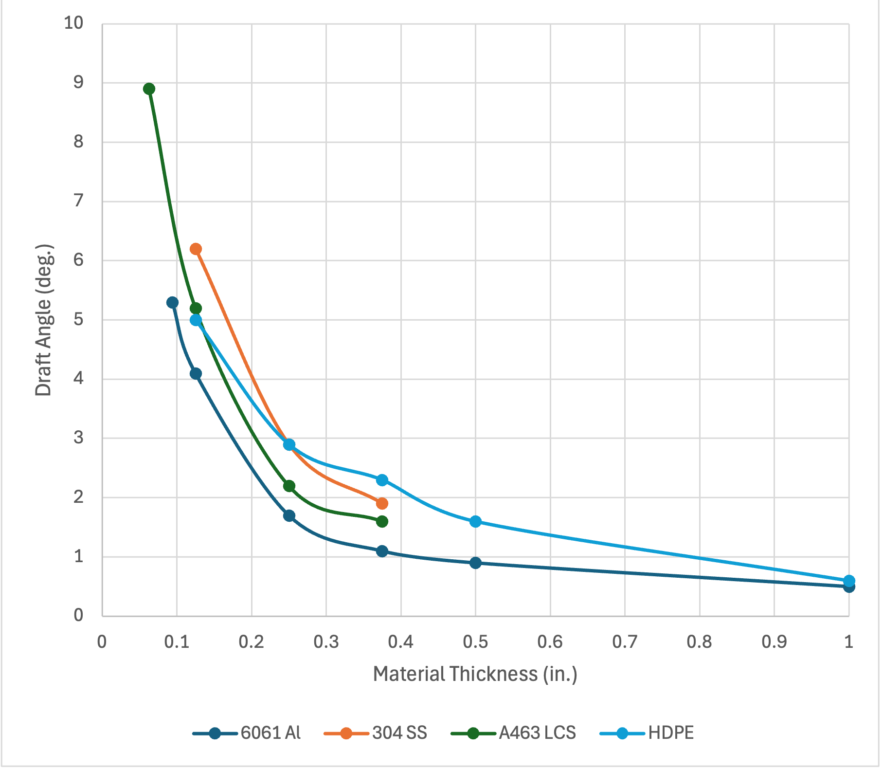
In general, we see that draft angle decreases as a material’s thickness increases. This trend is extremely clear in the graph below and is mirrored in previous testing performed on WAZER Desktop.
Figure 1: Draft Angle v. Material Thickness
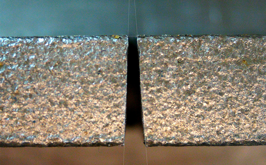
For a more qualitative illustration of this trend, photos of the ⅛” 304, ¼” 304, and ⅜” 304 are found below. Note, these images are not to scale. This set of photos helps illustrate how draft angle decreases as material thickness increases.
Figure 2: Stainless Steel
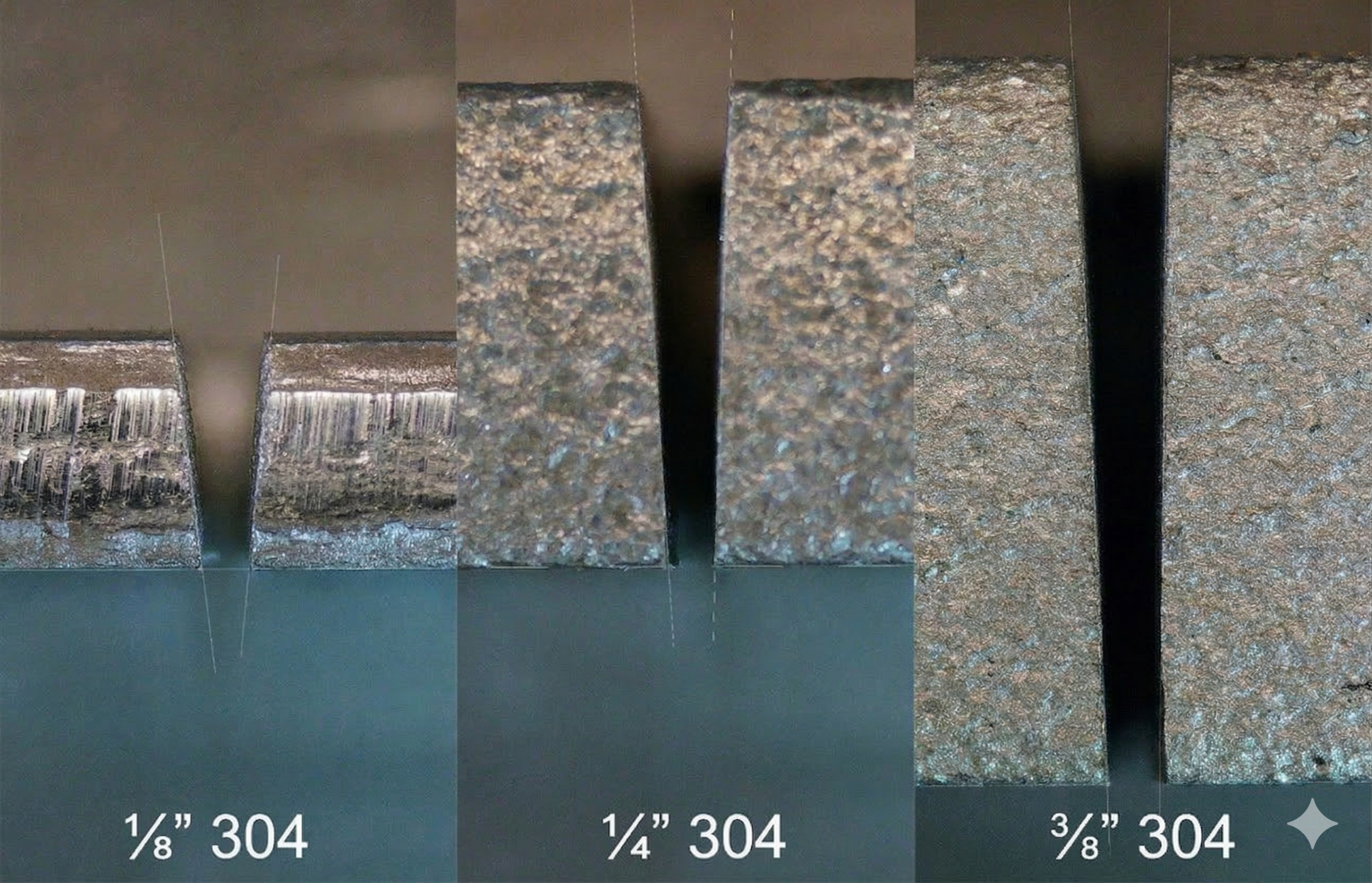
Table 1 below reports the material type, thickness, cut speed, average draft angle, average draft width per side, and abrasive consumed per inch of cutting for each sample from this investigation. Full data can be found in the appendix.
Table 1: Draft Angle Measurements – Materials and Thickness Tests
| Material | Thickness (in) | CutSpeed (ipm) | Avg Draft Angle (deg) | Draft Width per Side (in) | Abrasive Used (lbs/Inch) |
|---|---|---|---|---|---|
| 6061 Aluminum | 0.094 | 5.3 | 5.3 | 0.009 | 0.06 |
| 0.125 | 4 | 4.1 | 0.009 | 0.08 | |
| 0.250 | 2 | 1.7 | 0.007 | 0.17 | |
| 0.375 | 1.3 | 1.1 | 0.007 | 0.25 | |
| 0.500 | 1 | 0.9 | 0.008 | 0.33 | |
| 1.000 | 0.5 | 0.5 | 0.008 | 0.66 | |
| 304 StainlessSteel | 0.125 | 1.3 | 6.2 | 0.014 | 0.25 |
| 0.250 | 0.7 | 2.9 | 0.013 | 0.47 | |
| 0.375 | 0.5 | 1.9 | 0.012 | 0.66 | |
A463 Low Carbon Steel | 0.063 | 2.5 | 8.9 | 0.010 | 0.13 |
| 0.125 | 1.4 | 5.2 | 0.011 | 0.24 | |
| 0.250 | 0.7 | 2.2 | 0.010 | 0.47 | |
| 0.375 | 0.5 | 1.6 | 0.010 | 0.66 | |
| HDPE | 0.125 | 25.3 | 5.0 | 0.011 | 0.01 |
| 0.250 | 8 | 2.9 | 0.013 | 0.04 | |
| 0.375 | 4.1 | 2.3 | 0.015 | 0.08 | |
| 0.500 | 2.5 | 1.6 | 0.014 | 0.13 | |
| 1.000 | 0.8 | 0.6 | 0.011 | 0.41 |
How Does Cutting Speed Affect Draft Angle with WAZER Pro?
To help quantify draft angle’s relation to cut speed, our team performed a series of test cuts on the same 4 commonly used materials:
- 6061 Aluminum
- 304 Stainless Steel
- A463 Low Carbon Steel
- High Density Polyethylene (HDPE).
Each material was tested at a range of speeds across a single thickness. For each speed, 4 test cuts were performed and 8 draft angle measurements were recorded. The speeds tested in this investigation started at the stock speed reported on our materials specs page and tested down to 0.5 IPM at evenly spaced intervals.
At slow feed rates, cut speeds impact on draft angle is highly variable. There is no consistent trend across the materials and speeds tested. This variation is visible in the figure below.
Figure 3: Draft Angle v. Feed Rate (ipm)
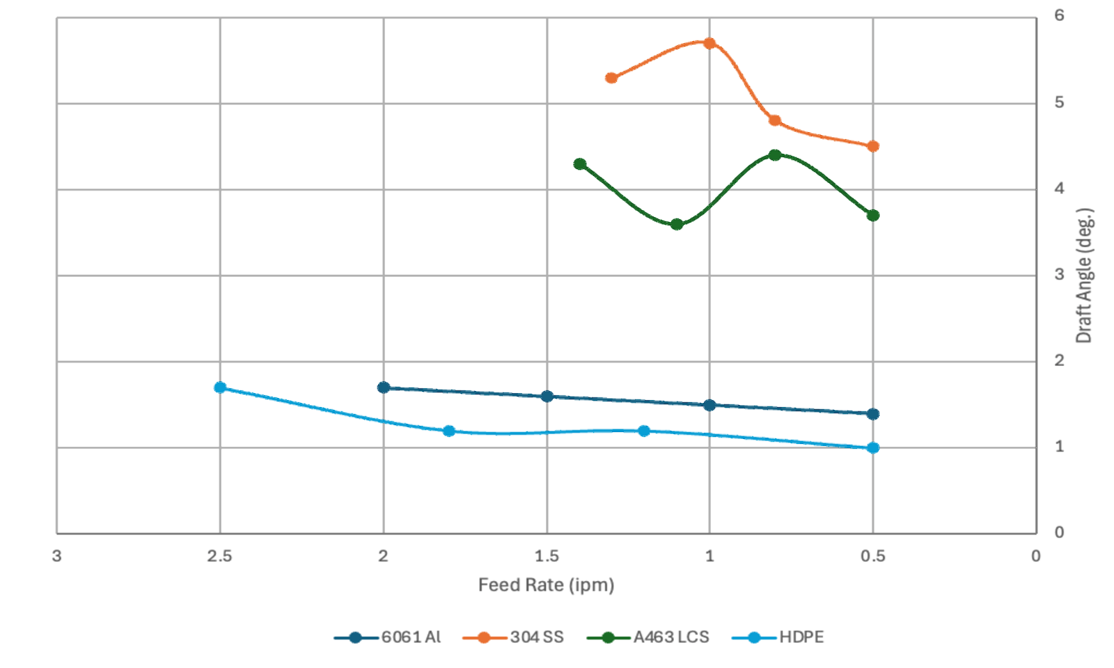
For aluminum and HDPE, there is a marginal decrease in draft angle as cutting speed decreases. However, as abrasive consumption is fixed per minute, and far less linear cutting is performed at the slower rate, this marginal change comes at the cost of much higher abrasive consumption.
For a more qualitative illustration of this trend in aluminum, photos of all 2.0, 1.5, 1.0, and 0.5 IPM samples are shown below. Note, these images are not to scale.
Figure 4: Aluminum
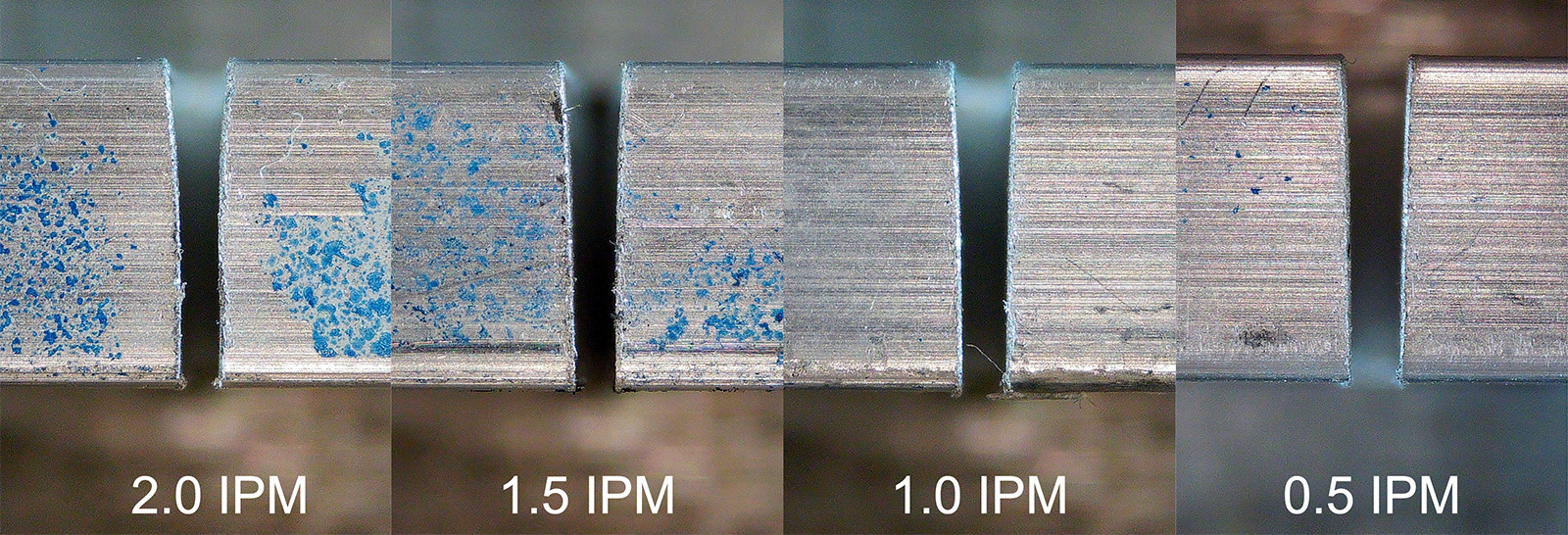
There is a visible, but minor change between the aluminum samples cut at 2.0 IPM (Left) and 1.5 IPM (Center-left). There is almost no change between the samples cut at 1.5 IPM (Center-left) and 1.0 IPM (center-right) and even less between 1.0 (center-right) and 0.5 (right).
There is no trend visible in the steel and stainless steel cuts. Slower cutting speeds do not provide a predictable change in draft angle of any form. Slower cutting speeds also result in higher abrasive consumption for these materials.
For a more qualitative illustration of this trend in stainless, photos of all four samples are shown below. Note, these images are not to scale.
Figure 4: Stainless Steel
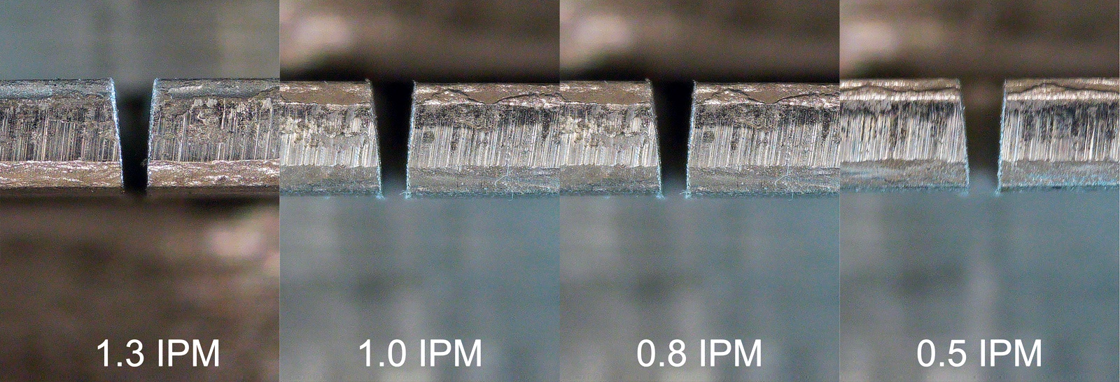
There is almost no perceptible difference between the fastest cut sample at 1.3 IPM (Left) and the slowest cut sample at 0.5 IPM (right). There is however, a large change in abrasive consumption per inch of cutting.
This abrasive consumption for all samples is reported in the rightmost column of the table below.
Table 2 below reports the material type, thickness, cut speed, average draft angle, average draft width per side, and abrasive consumption for each sample from this first investigation.
Table 2: Draft Angle Measurements – Cut Speed Tests
| Material | Thickness (in) | CutSpeed(ipm) | Avg Draft Angle (deg) | Draft Width per Side (in) | Abrasive Used (lbs/Inch) |
|---|---|---|---|---|---|
| 6061 Aluminum | 0.250 | 2.0 | 1.7 | 0.007 | 0.17 |
| 0.250 | 1.5 | 1.6 | 0.007 | 0.22 | |
| 0.250 | 1.0 | 1.5 | 0.006 | 0.33 | |
| 0.250 | 0.5 | 1.4 | 0.006 | 0.66 | |
| 304 StainlessSteel | 0.125 | 1.3 | 5.3 | 0.012 | 0.25 |
| 0.125 | 1.0 | 5.7 | 0.012 | 0.32 | |
| 0.125 | 0.8 | 4.8 | 0.010 | 0.43 | |
| 0.125 | 0.5 | 4.5 | 0.010 | 0.66 | |
| A463 Low Carbon Steel | 0.125 | 1.4 | 4.3 | 0.009 | 0.24 |
| 0.125 | 1.1 | 3.6 | 0.008 | 0.30 | |
| 0.125 | 0.8 | 4.4 | 0.010 | 0.41 | |
| 0.125 | 0.5 | 3.7 | 0.008 | 0.66 | |
| HDPE | 0.500 | 2.5 | 1.7 | 0.015 | 0.13 |
| 0.500 | 1.8 | 1.2 | 0.010 | 0.18 | |
| 0.500 | 1.2 | 1.2 | 0.010 | 0.28 | |
| 0.500 | 0.5 | 1.0 | 0.009 | 0.66 |
The relationship between cut speed and draft angle is not consistent across materials. Some materials, like aluminum and HDPE show a small but consistent decrease in draft angle as cut speed decreases. It should be emphasized that these changes are minor at best and come at the cost of significantly increased abrasive consumption.
Low carbon steel and stainless steel show far less predictable behavior when slowing cut speed. It is beyond the scope of this article to attempt to explain the differences in this behavior but it reinforces that performing a test cut is always a good idea if draft angle is key to your application.
Conclusions
Draft angle will be present on all parts cut on WAZER Pro but the magnitude of this draft will vary greatly with material type and material thickness. Cut speed will have a minimal or unpredictable impact. We always recommend doing a test cut if draft angle is critical to your application but this article should serve as a basic guide.
Still have questions about draft angle? Connect to a sales engineer now!