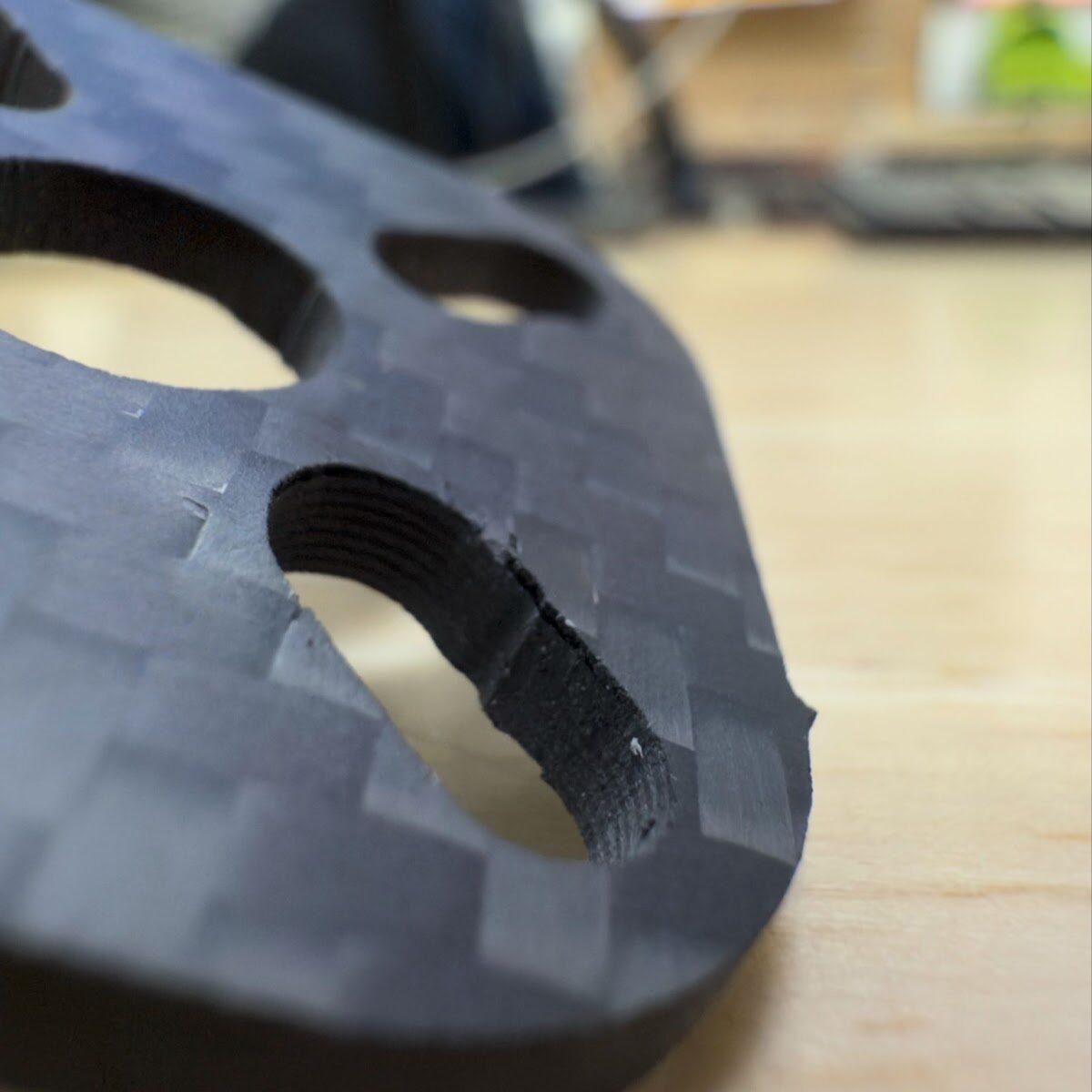
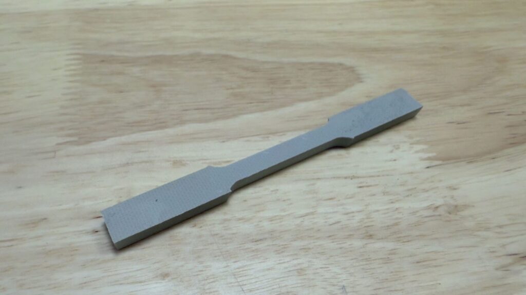
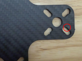
Composite materials like FR-4/G10 and Carbon Fiber sheets are materials composed of layers of woven fibers reinforced with a resin, epoxy, or other solid polymer. When using a waterjet to cut these materials, they can often delaminate or separate. This delamination occurs during the initial “pierce” at the start of the cut. A great example of this delamination can be seen below.
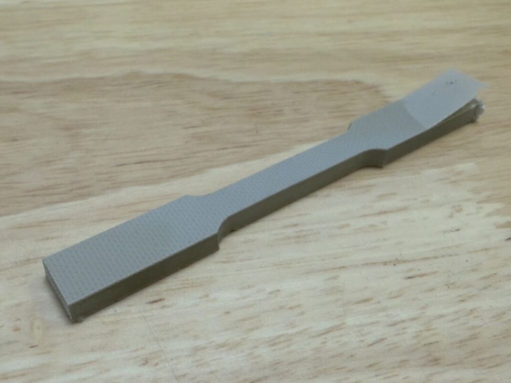
This delamination occurred while cutting a simple dogbone profile. While cutting simple profiles, there is an equally simple method for preventing them. Starting off the edge.
Start Off the Edge
As stated above, and backed in literature, delamination of composites during abrasive waterjet (AWJ) processes occurs when high pressure water without abrasive mixed in impacts the raw material. This phenomenon is called water hammering. To eliminate the impact of water hammering, an extra long lead can be used to move the pierce off of the material. This will eliminate the stress during water hammering and should improve cut quality. These leads can be manually drawn into the profile in CAD or a custom material profile can be created in WAM with an extra-long lead-in. Listed in the table below are two .dxf files and two .gcode files. These examples illustrate a standard cut and a “long lead” cut.
| Standard Cut | Long Lead | |
| DXF | Dogbone.dxf | DogBone-ManualLead.dxf |
| G-Code | DogBone-NoLead.gcode | DogBone-ManualLead.gcode |
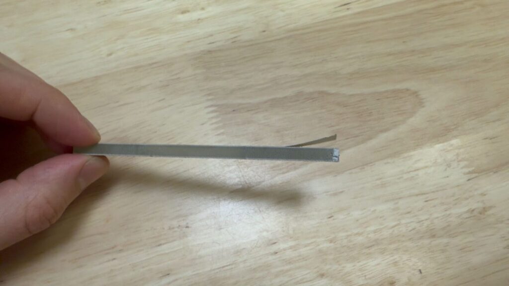
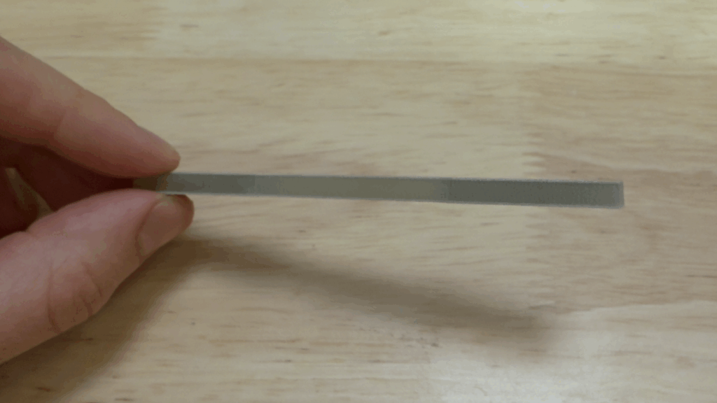
Cutting these files on similar sheets of FR4 using stock cut settings resulted in delamination on the standard piece and no delamination on the “long lead” piece (shown below).
This method, like all delamination prevention methods, is not 100% effective. It is also unsuitable for more complex geometries. For parts with internal voids, like drone frames, a more complex delamination prevention method is needed.
Pre-Drill Pierces
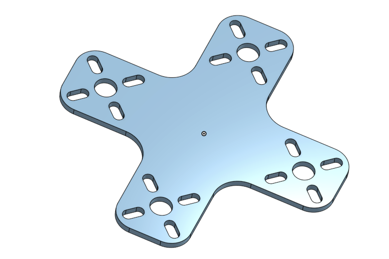
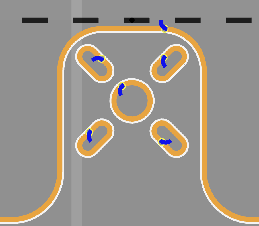
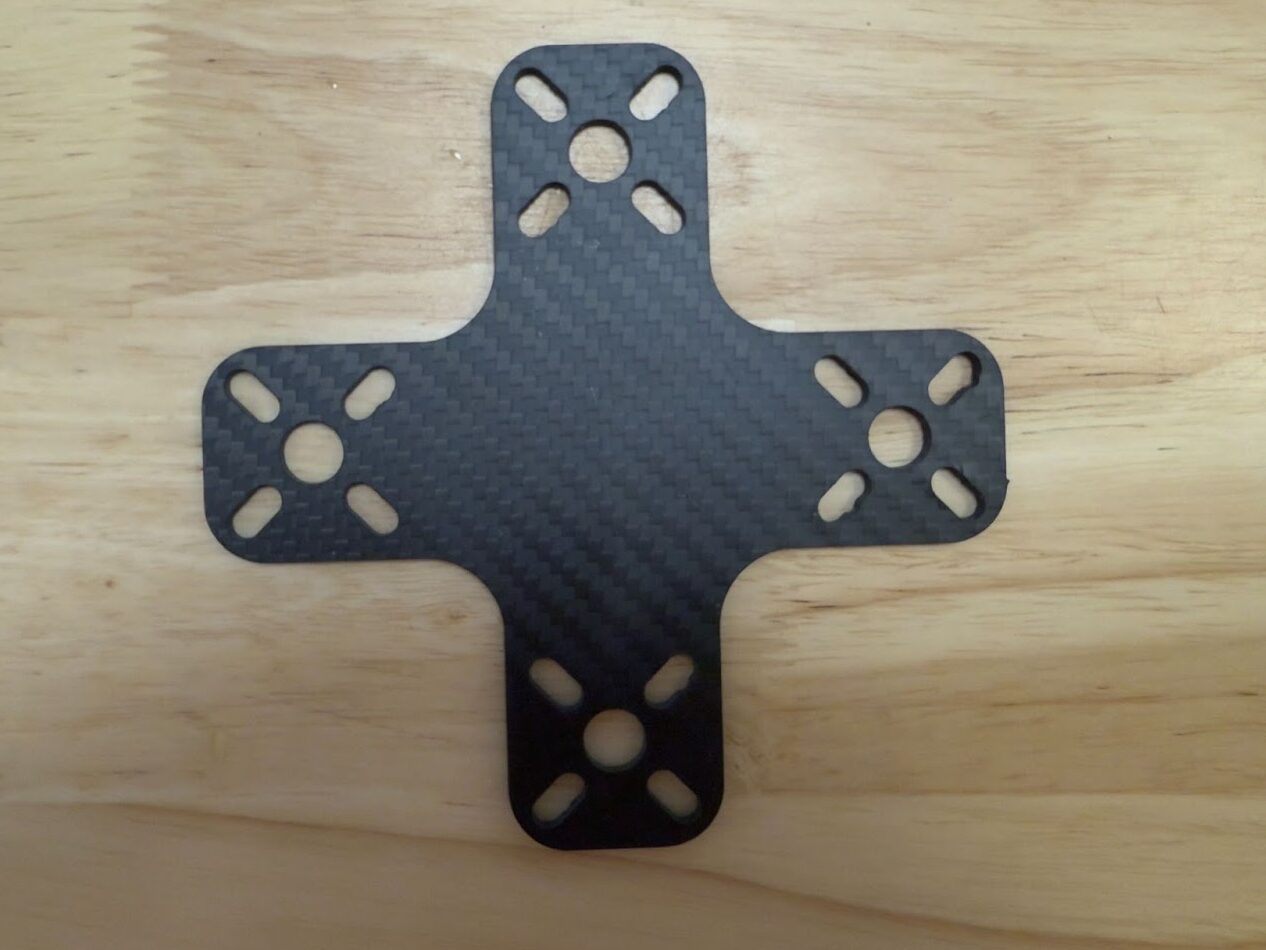
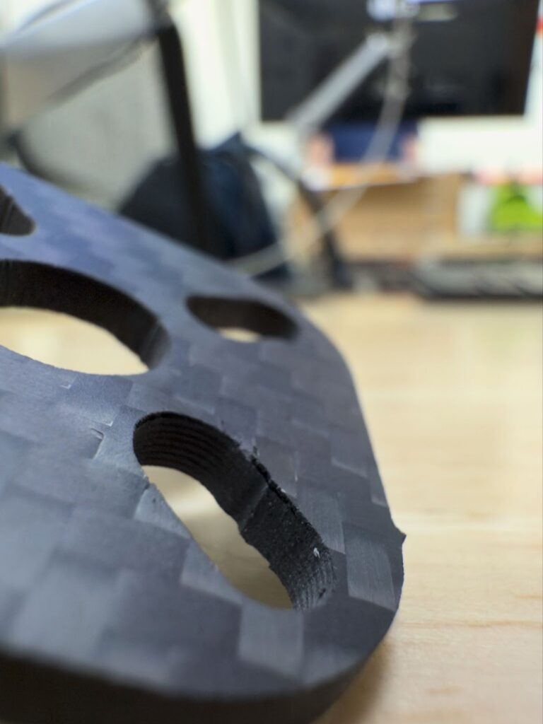
This drone is a fairly complex part to cut using a waterjet. It has a total of 21 pierce points, all of which can result in delamination. When cutting this piece in 3mm carbon fiber it delaminated at 6 separate piece points including a large separation shown below.
To try to avoid this, some industrial scale waterjets have pneumatic drill attachments to precisely predrill all piece points before moving on to a traditional AWJ operation. This “pre drilling” could also be done quite easily with a CNC mill as a complement to a WAZER waterjet. For low production runs or single use prototypes we have developed a method which will accomplish a similar result using only WAZER, a piece of sacrificial material, and a composite-specific drill bit.
This section of the article will highlight the basics of how to move through this procedure, starting with a .dxf of your part, creating the g-code of the final AWJ operation, using that g-code to generate a .dxf of the cut path, before using that .dxf to generate a map of all the pierces in your part. We will then use that pierce map and WAZER to cut a template in a piece of sacrificial material (we used ⅜” acrylic) to use as a drilling guide. We will then use that drilling guide to accurately predrill all of the pierce points before finally cutting the original part.
This procedure has a lot of steps and is fully explained in a separate article linked here. What follows highlights the main steps to give readers a broad understanding of the process of pre-drilling pierce points.
Step 1
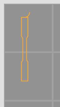
Import your final part geometry into WAM taking care to examine the position of all leads and position the overall geometry relative to the Absolute Locating Jig. The leads should be the same length as your nominal drillbit size and positioned in such a way that the drill bit will not interfere with the part geometry. Then, generate the G-Code as normal. You can choose to create a custom material profile with 1 second pierces but this step is not explicitly necessary.
The G-Code created in step 1 will serve as the base of all further steps. It is important to ensure that this initial G-Code file is correct before moving on to the next step. We will refer to this G-Code as “XX_finalpart.gcode”
Step 2
Use https://cnc-apps.com/en/app/convert2dxf to create a .dxf file containing the cut path using “XX_finalpart.gcode”. We recommend naming the resulting file something like “XX_toolpath.dxf” to help keep track of the .dxf files.
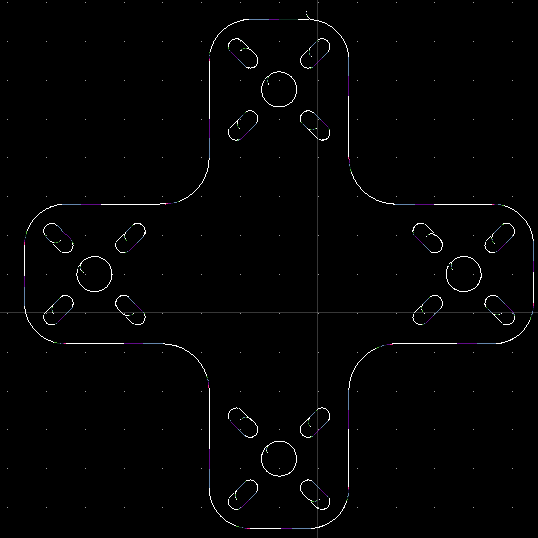
After creating this “XX_toolpath.dxf” we will import the drawing into a CAD software of our choice (we use Q-Cad in the detailed procedure) to create a cut file of only the pierces. This is the hard part! If you nail this the rest should be easy so read carefully, take your time, and double check your work.
Step 3
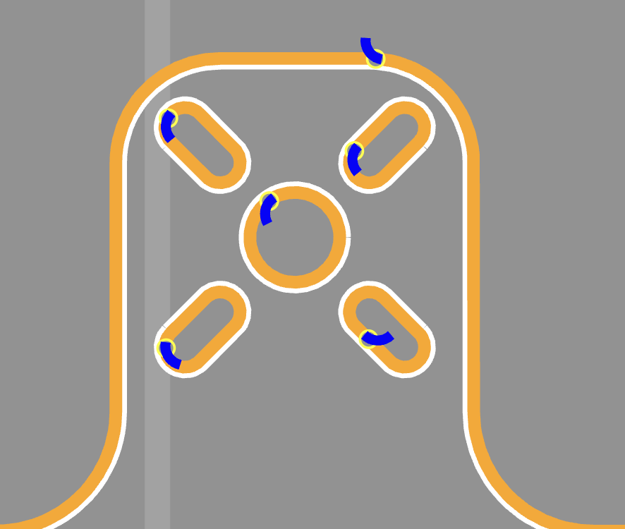
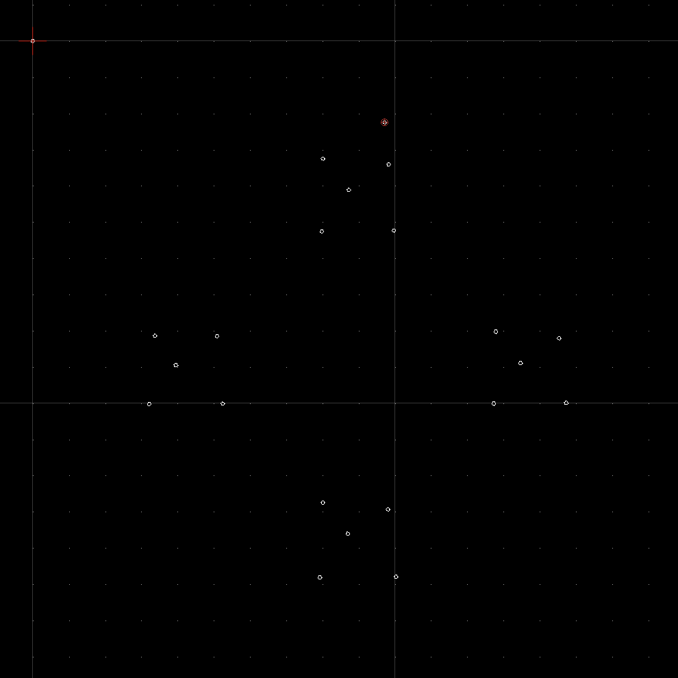
Import “XX_toolpath.dxf” into Q-Cad and follow section 4 of the instructions. Make sure to set the drawing units to mm! Then, create a new layer and place 1mm circles with their centerpoints at the end of each lead. These points will be used to cut pierces into our sacrificial material in order to create a dimensionally accurate template. Also put a 1 mm circle centered at the origin (0,0). This will ensure that the .dxf is automatically positioned correctly in WAM. By separating these circles into a second layer, the next step, deleting all of the cut path geometry, can be accomplished in a single operation. Finally, double check that the only geometries in this file are the 1 mm circles and save this .dxf as a new file. We recommend naming it something like “XX_template.dxf”
This “XX_template.dxf” file will be used to create a template using WAZER and some inexpensive sacrificial material. It could also be used as a method of locating the drill points to be used in a CNC mill or other tool but we will focus on manual drilling. In this case, we will be focused on using WAZER and a hand drill to create a template in a piece of 5mm delrin.
Step 4
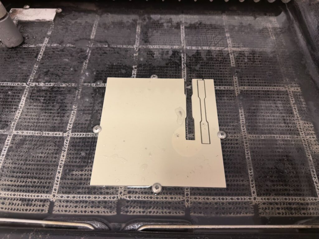
To cut your jig, simply import “XX_template.dxf” into WAM and treat it as a regular part file. The 1 mm hole we put at 0,0 should automatically position the part in its correct position. Do not move it from 0,0! Moving the part will alter the alignment between “XX_finalpart.gcode” and the template file. Select your materials as normal (coarse quality is perfect for this type of cut) and save the resulting file as “XX_jigpierce.gcode”.

Step 5
We have now created the two G-Code files we will need to complete this project and we can now move over to our waterjet to physically cut the parts.
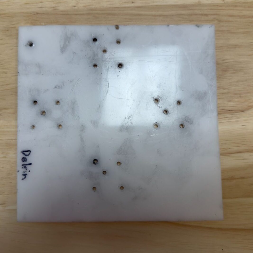
We will first use “XX_jigpierce.gcode” to create a blank jig. This blank jig will contain all of the centerpoints needed to create the final jig.
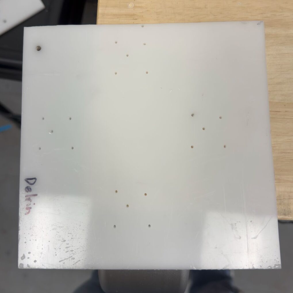
Step 6
After cutting “XX_jigpierce.gcode” we will use a hand drill (or drill press) and a regular multimaterial drill bit to widen these to our final 3 mm diameter.
Step 7
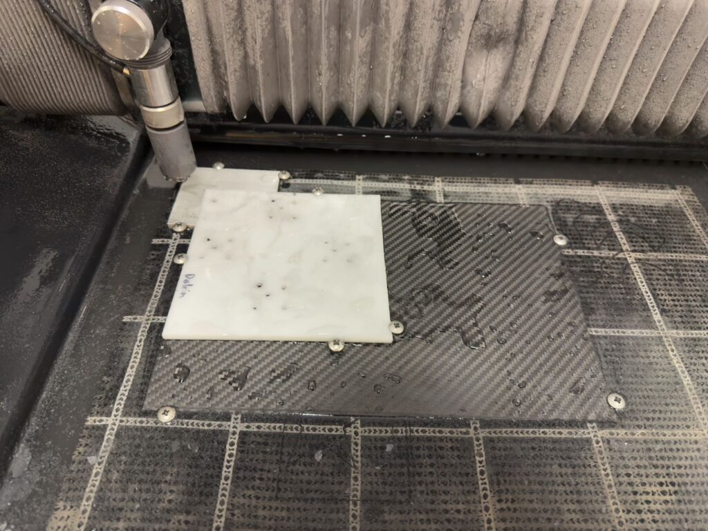
We will then position both the raw material (3mm Carbon Fiber) and our jig into the absolute location and use our Composite drillbit to drill out all the pierce points in the carbon fiber. These composite drillbits are slightly expensive but well worth it in the time they save for this operation.
Step 8
Finally, remove the jig, ensure the carbon is positioned correctly in the absolute locating jig, and cut “XX_finalpart.gcode”. The holes we just drilled in the raw material should align perfectly with the pierce points in our G-code and prevent the raw material from delaminating. The jig and cut file can be reused for batch operation and the jig could be made of a more robust material if you so desired.
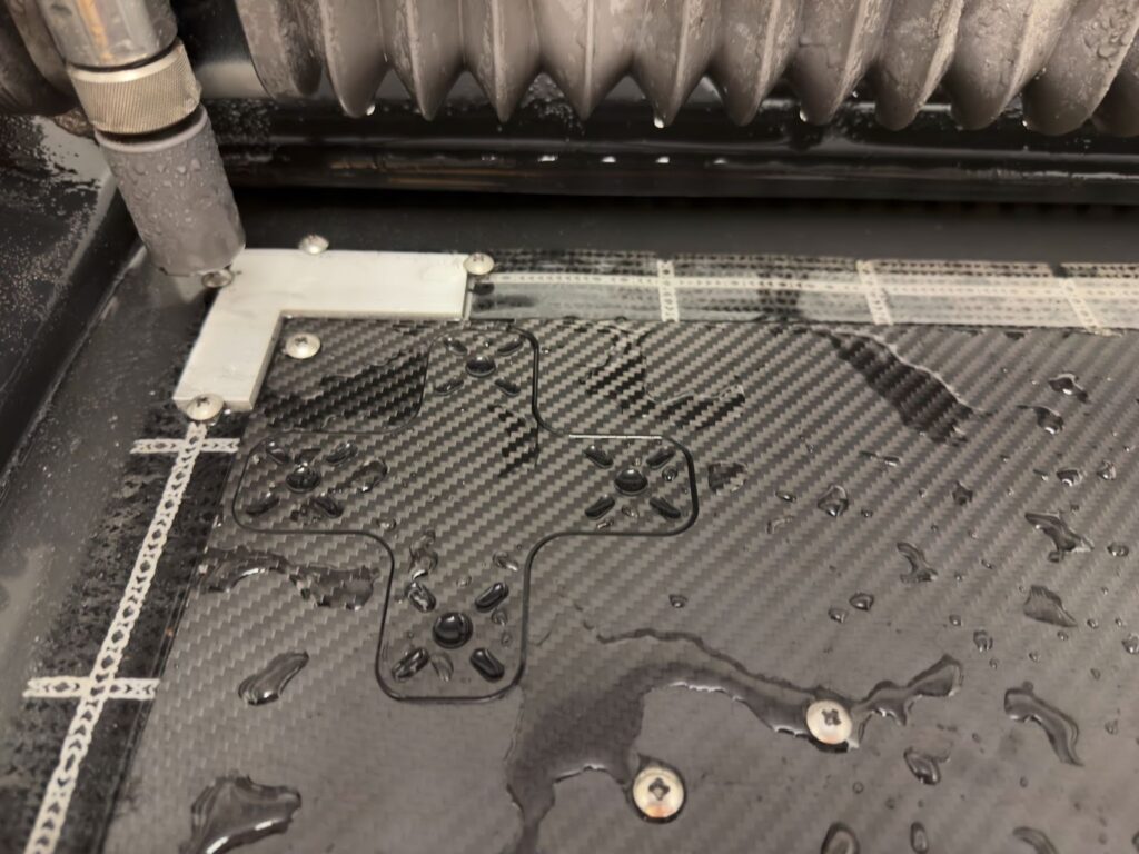
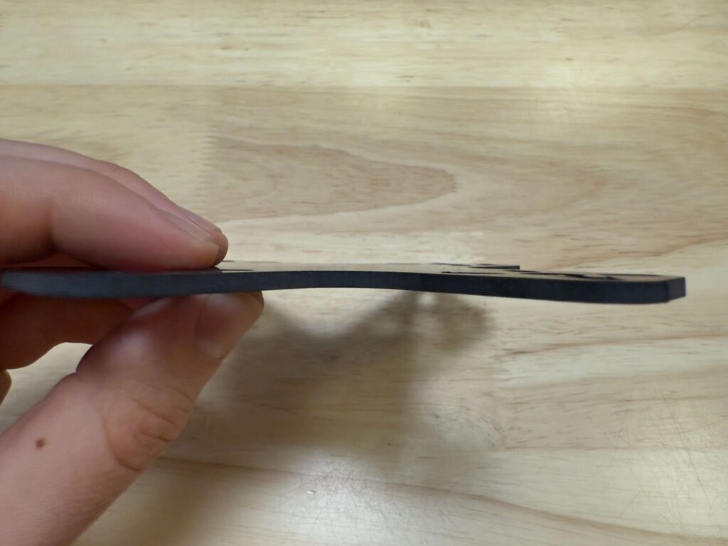
Our “XX_finalpart.gcode” cut without issue and looked like this immediately following the cut on WAZER Desktop.
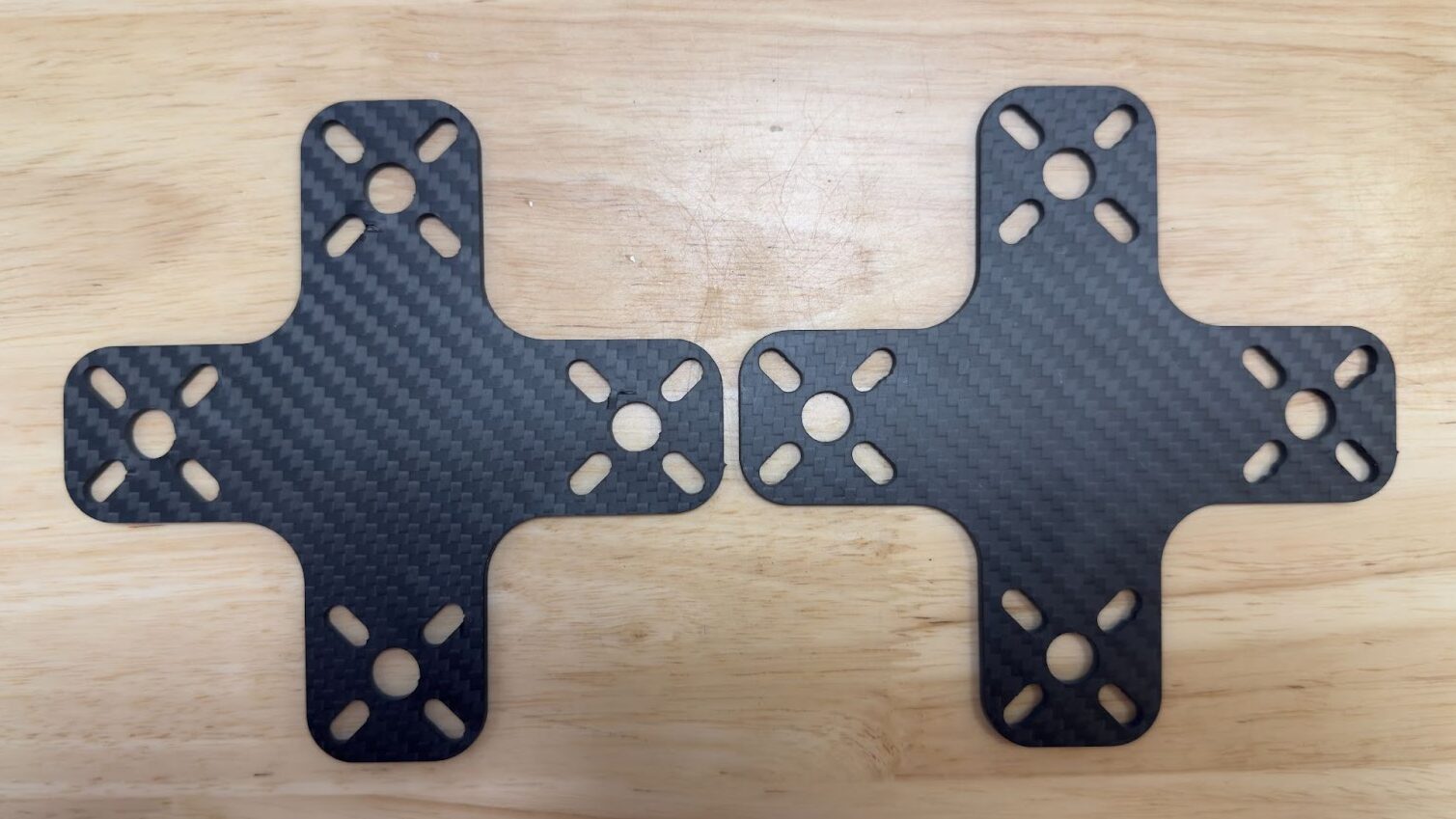
It saw a decrease from 6 delaminations to only 1 small delamination. There was also no large delamination like on the sample cut with stock speeds.
A side by side comparison of the two samples is shown below.
Conclusion
While no delamination prevention method is 100% perfect, these two should provide excellent results in most applications. It is always worth experimenting with a few suppliers of any composite as they are a highly variable raw material.
If you have any other questions regarding cutting composite materials on a WAZER Waterjet please reach out to us and we’ll connect you with a sales engineer ASAP!