Overview
An earlier tutorial introduced the concept of “Offset” and how offsets matter when cutting glass for different joining methods. Yet there is another aspect to consider when it comes to introducing more parts to our glass art – tolerance stack-up.
Whether we design digitally or by hand, the design dimensions of a part will never be 100 percent exact in the real world. Each physical part has a slight deviation from its design dimensions depending on the material, fabrication method, or environmental factors. This range of deviations is known as “tolerance”. In a multipart assembly, each part has its own machining tolerances and when combined in the assembly, the tolerances add up. The added-up tolerance interferes with the assembly accuracy and overall dimensions. This is known as tolerance “stack-up”.
In this tutorial, we will explore how the tolerance stack-up affects the assembly of a multipart stained glass design and how we can take the tolerance stack-up into consideration and make intricate cool designs.
This tutorial contained cut files for a pixelated Mario design and is recommended for the materials listed above. A step-by-step guide is provided to guide and teach us manufacturing considerations when cutting glass.
Tools Needed
- File
- Isopropyl alcohol
- X-acto knife
- Cardboard
- Pins
- Copper tape of ¼ inch thickness
- Solder 50/50 with a diameter of 0.125 inches
- Flux
- Soldering iron
What is Tolerance Stacking?
Before moving forward with the tutorial, let’s define tolerance stack-up. Tolerance stack-up refers to the process of adding tolerances together to determine the cumulative effect of tolerances on a part prior to manufacturing. When we have an assembly with multiple interacting parts, making sure that everything will fit correctly is very important. In the case of stained glass art, there will be multiple pieces that fit within each other or adjacent to each other and it is important to have large enough space to allow for solder or epoxy to fit in the gaps.
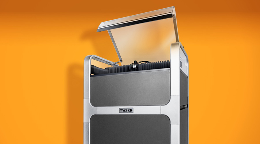
To achieve the desired fit and eliminate tolerance stack-up, all we need to do is use WAM. When using WAZER to cut glass, there is a kerf due to the water and abrasive stream that does the actual cutting. The kerf of the WAZER on glass is 0.06 inches which are 0.022 inches more than the kerf of the WAZER nozzle. The kerf of glass is a lot larger than what is ideal for stained glass artwork, therefore one way we can control where the kerf lands and use it to our advantage is by selecting the appropriate cut path. WAM has three options for cut paths, outside, centerline, and inside. The outside cut path is appropriate when tolerances have been accounted for in the design process. The inside cut path is appropriate for special cases where the cut path needs to be offset for reasons other than the kerf. The centerline cut path is the ideal cut path for a design where machine tolerances have not been accounted for. In the case of this tutorial design where the line work is shared among the pieces, the centerline cut path is the best solution as it will allow for 0.038 inches of space between the pieces and that is enough to accommodate the solder and copper tape. The centerline cut path provides a negative tolerance to the original dimensions of the pieces.
Process
Setting Up Cut Files in WAM
- Download the DXF files.
- Unzip the files and import them into WAM.
- There are four files labeled with the color of glass used in this tutorial.
- For all the colors we will cut, the setup will be the same:
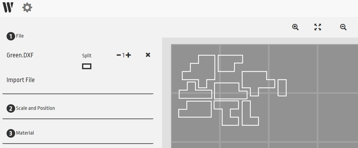
- Import the file
- Size and position to the left top corner of the cutting area
- Then, select the material in the pre-existing database of materials, Ceramics and Stone → Glass, Soda Lime →, and a thickness of 0.25 inches.
- For the cutting path, choose a centerline cut path.
- No tabs
- For the cut quality, choose a fine cut for a smooth finish with minimal chipping on the edges.
- Download the G-CODE.
- Load the 4 different G-CODE files onto the SD card.
Cut Pieces/Tips
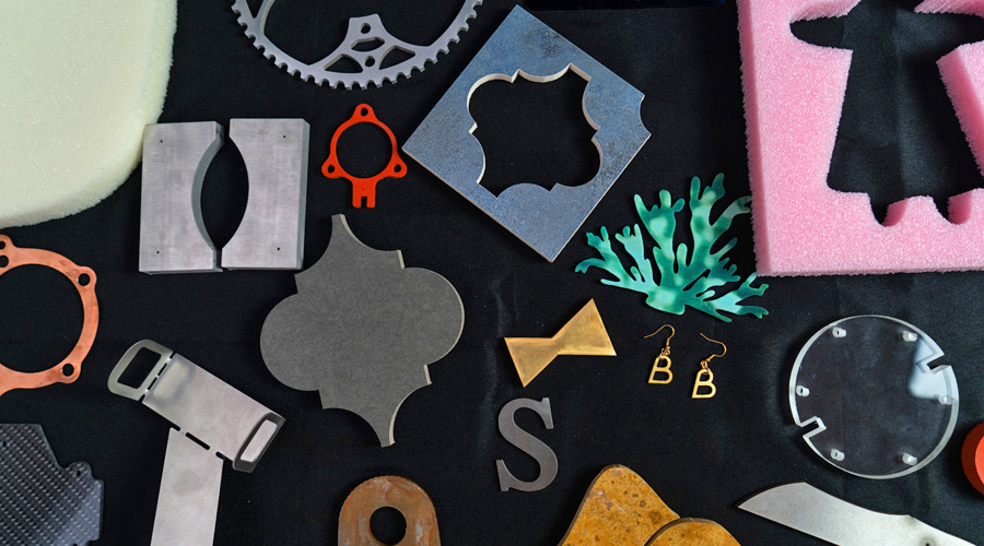
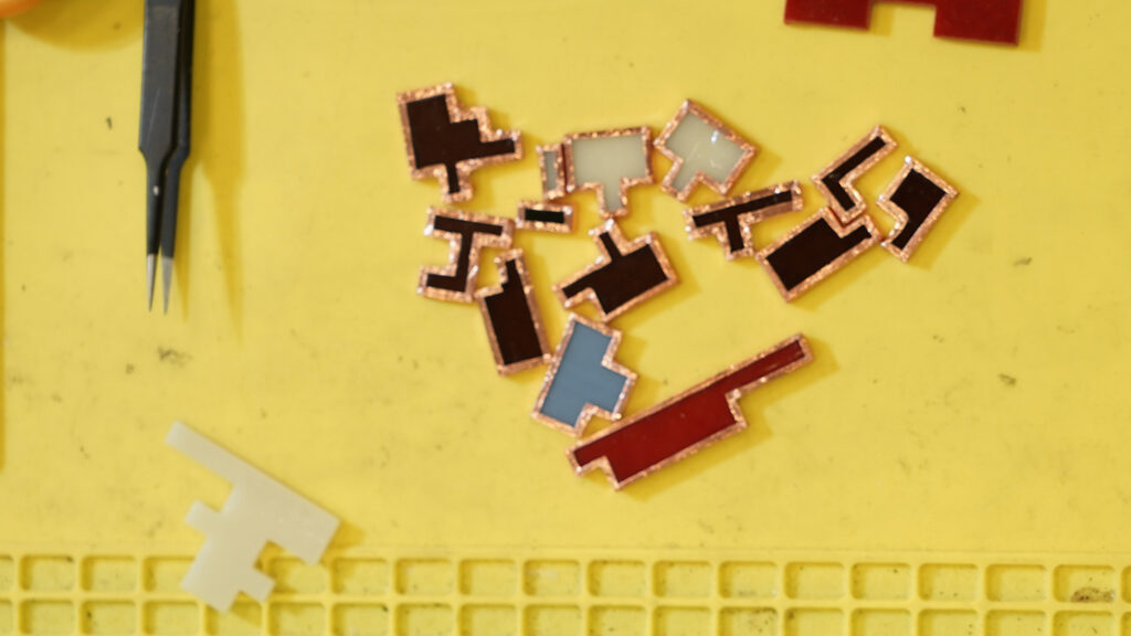
The cut pieces we should have are 2 blue pieces for the frame, 6 yellow pieces, 2 red pieces, and 9 brown pieces. If we assemble the pieces according to the design adobe, it is observed that the pieces have a sufficient gap to allow for copper tape and solder or epoxy. If we were to cut the pieces using an alternative cut path, the tolerances would have been too tight resulting in pieces falling out of the frame.
Post-Processing
- Wash off the abrasive and remove the cut pieces from the machine
- Using a file, file away any noticeable notches from the pierce points
- Thoroughly clean the glass piece edges and faces using isopropyl alcohol. This will help the copper tape adhere better to the glass surface.
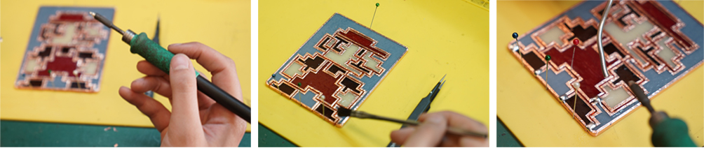
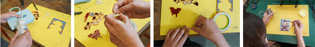
- Apply copper tape on the edges of all the pieces. Use the X-acto blade to refine the tape edges and add additional copper tape wherever necessary.
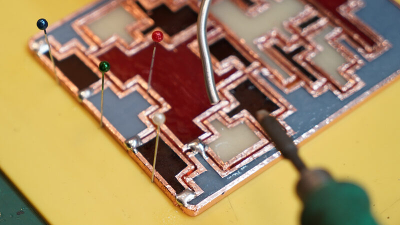
- Lay out the assembled design on the cardboard and place pins on the outer corners of the design to secure it.
- Tack the corners of each piece together to get the approximate shape and then solder everything.
- Continue soldering all edges until all pieces are joined together.
Final Assembly