Fine-tuning your cut settings is key to getting the most out of your WAZER. Like any CNC tool, dialing in performance requires experimenting with variables until you find the ideal setup for your specific application. In waterjet cutting, it’s not just about selecting the right material. Your tab and lead-in settings play a crucial role in achieving clean, precise results.
What are Lead-Ins and why are they important?
Lead-ins allow the waterjet to pierce away from the part’s cut path, minimizing edge defects and ensuring a cleaner final result. Typically, this is paired with a tab to hold the part in place during cutting. But what if you don’t want a tab?
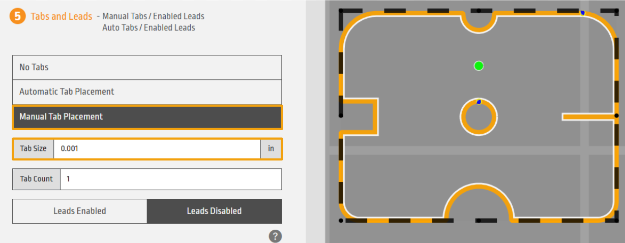
The zero tab width method is a clever workaround. By setting the tab width to 0.001″, WAM is “tricked” into applying a lead-in without leaving any tab material behind. This allows for a clean entry without interfering with the part features.
WAM Behavior Explained
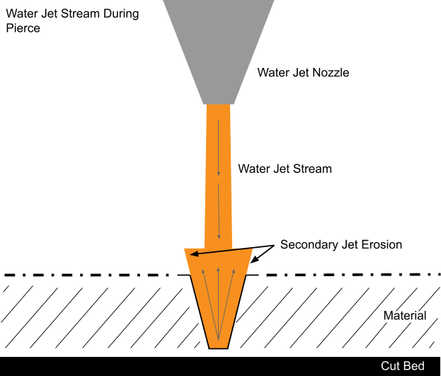
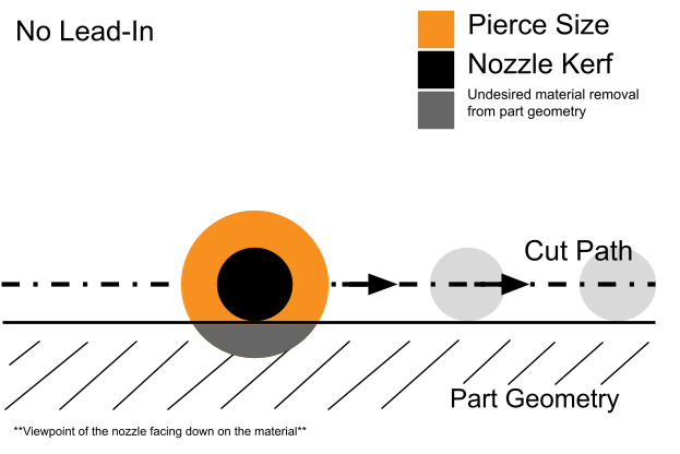
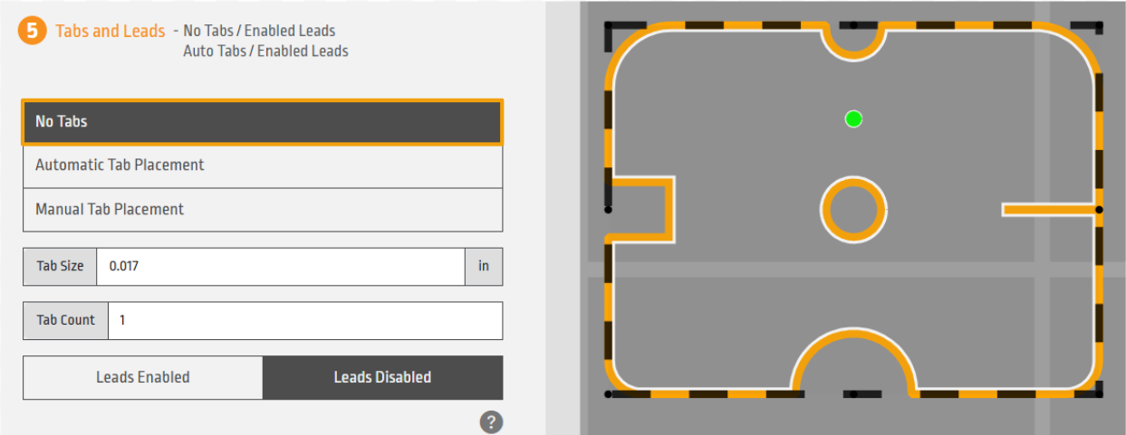
By default, if the “No Tab” setting is selected, WAM does not put a lead at the pierce point. This means that the water jet pierce will be right on the cut path, which will damage the edge. With the pierce being the long timespan that the nozzle spends in one location, it always will end up being slightly larger than the cutting kerf of the machine. This is because as the water jet makes its way through the material, the abrasive particles in the stream erode the hole, causing it to widen. In longer pierces, the water jets’ interaction with the hole walls and the remnants of the primary high velocity stream can cause unintended erosion. This is known as Secondary Jet Erosion.
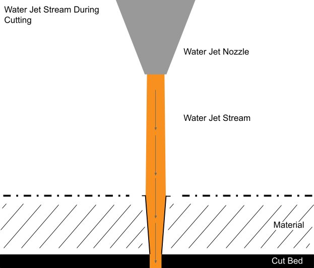
Once the cut begins and the water jet is moving, the kerf width becomes much more consistent and narrow, matching the stream diameter and parameters more closely.
No Lead-In vs. Lead In
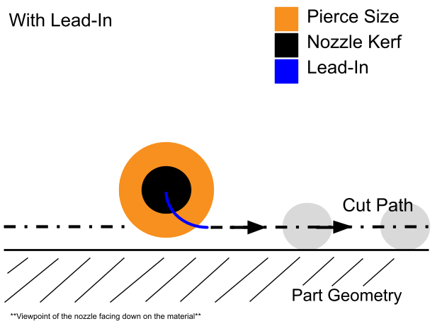
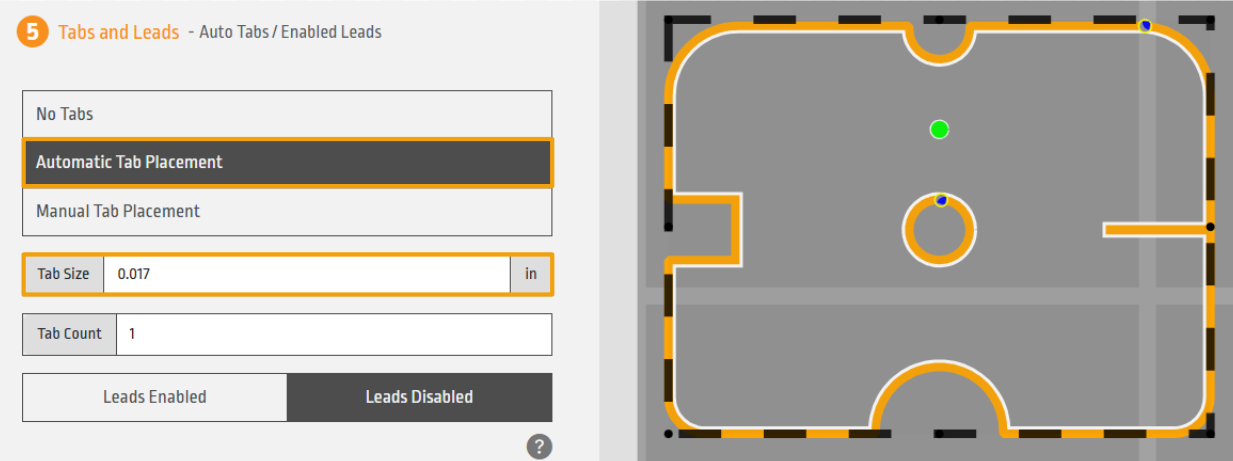
With no lead-in, the water jet pierces directly on the part’s cut path resulting in a visible defect on the finished edge of the part. A lead-in solves the issue of the secondary jet erosion by moving the pierce point away from the actual cut path of the part. The machine starts the pierce off to the side, on a small approach path that leads into the part’s actual outline. Then the jet moves into the part using the standard kerf width which preserves a smooth and consistent edge around the entire shape.
Zero Tab Width Trick
In this article, we’ll explore the three lead-in settings available in WAM and how each impacts cut quality of the part, particularly for internal features like holes and for the final outline of a part. We’ll also introduce zero tab width, a neat little trick that allows you to retain lead-ins without leaving behind a tab, offering greater control over where and how your cut begins.
WAM Lead-In Settings
After importing the correct file into WAM, apply the necessary material settings and move to the “Tabs and Leads” menu. In the “Tab Size” field, the tab width can be adjusted regardless of the material profile presets. Note that lead-in length cannot be adjusted in this menu.
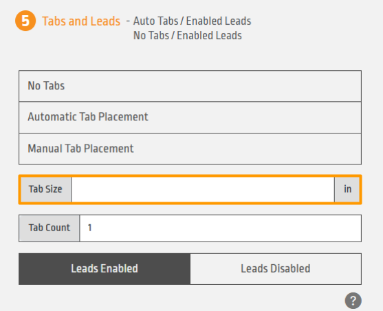
To make the tab width effectively zero, you need to input 0.001 inches or 0.001 millimeters.
Three Test Cuts: The Three Tab Settings
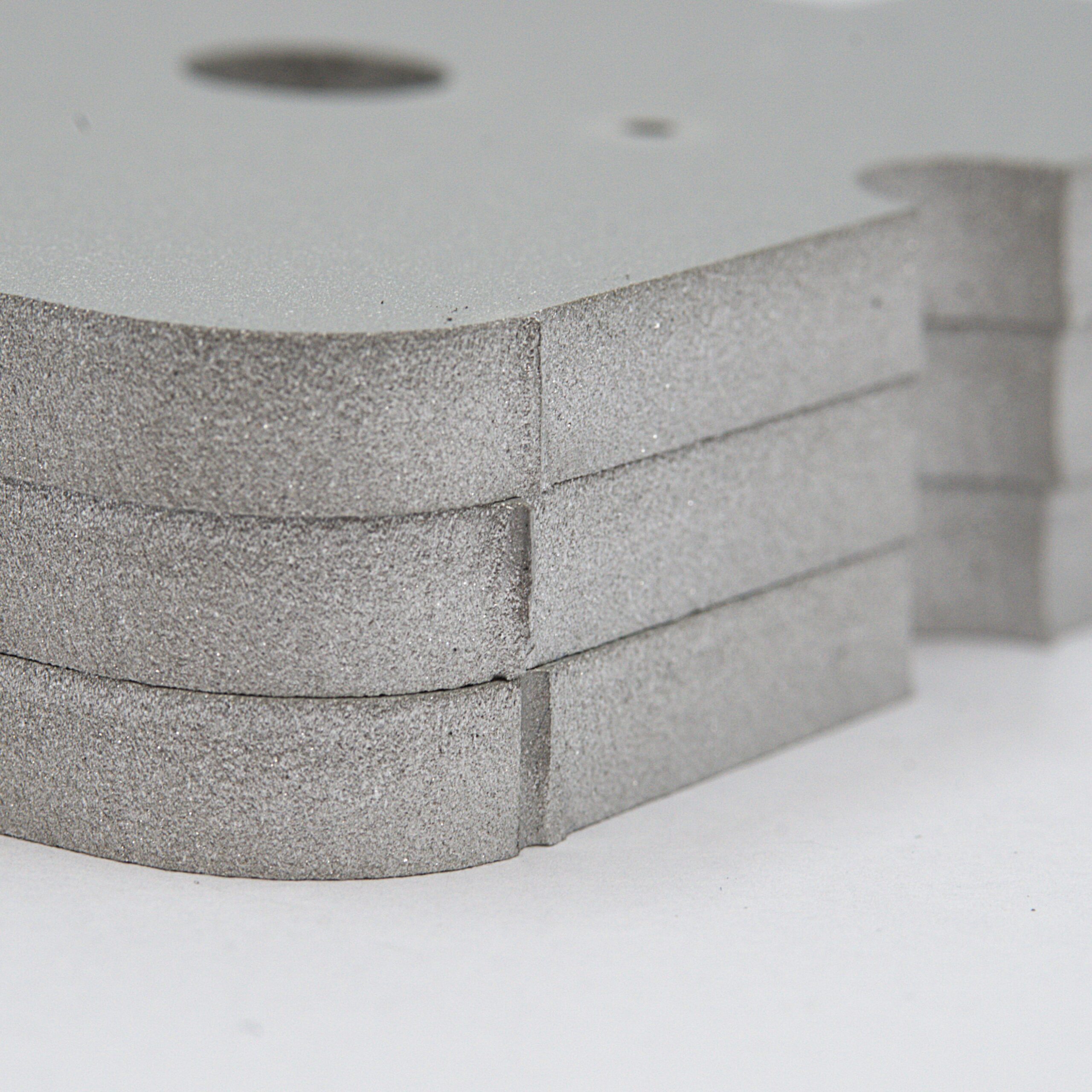
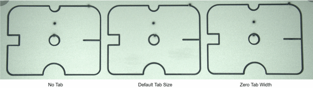
To assess the effect of the three different tab settings on edge quality, two features were compared: the circle cutout and the final outline of the part. Three sample parts were cut from 0.25” thick Aluminum: a no tab sample, a default tab width sample and a zero tab width sample.
No Tab
Default Tab
Zero Tab Method
GCODE Visualisation of the Two Key Features
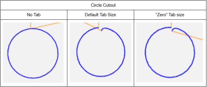
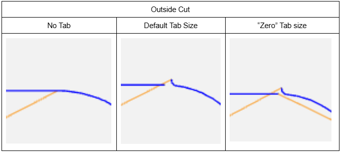
The visual representation of the tab sizes in WAM might not be that drastic, so to better understand what the machine will be doing, NC Viewer was used to closely observe the tab and lead in settings on the circle cutout and the outside cut. Looking at the features in NC Viewer, we can see the path difference between the three cutting options for the two features.
Cut Results
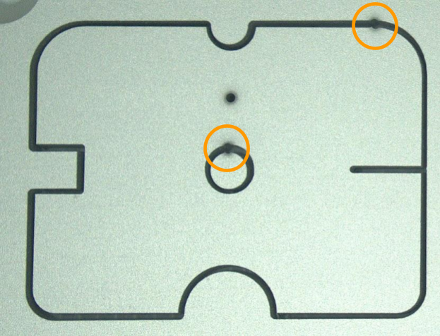
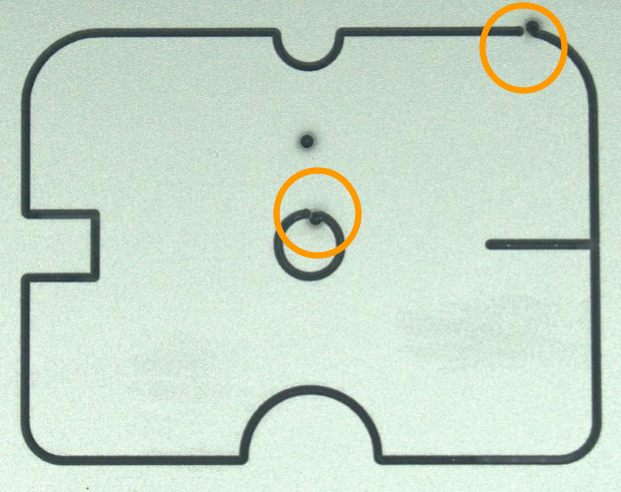
Looking at the Sample Profile with no tab, in the circles, the overcutting can be clearly seen in the key features.
In comparison to the default setting which initiated the lead-in presets of the material profile, the pierce point did not overcut into the final part. That being said, there is material to remove and post process to detach the piece from the stock material.
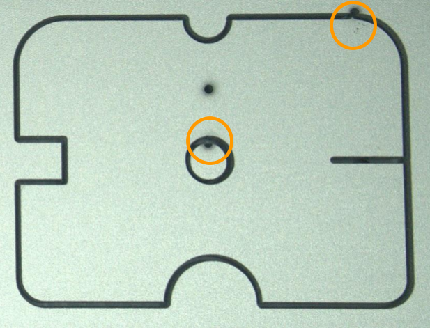
Finally, with the Zero Tab Width method, the extra material is removed while initiating the lead in and preventing overcutting defects on the part edge.
Conclusion
The Zero Tab Width method gives you the best of both worlds: clean entry cuts from lead-ins and no tab remnants to deal with. The Zero Tab width should not be used when cutting multiple pieces out of a sheet of material as we do not want the parts to move or interfere with the nozzle as it is cutting other areas of the material. Whether you’re cutting delicate internal features or precise outer profiles, this trick is a powerful addition to your WAM workflow.