
As a new drone enthusiast, I often crash because of my lack of experience with flying. The cheap plastic frames available online are simply not forgiving when it comes to crashing into stationary objects at high speeds. Since the part that is most likely to be damaged during a crash is the frame, I wanted to create my own cost-effective drone frames. To make the frames even more durable, I chose to make them out of Carbon Fiber instead of plastic.
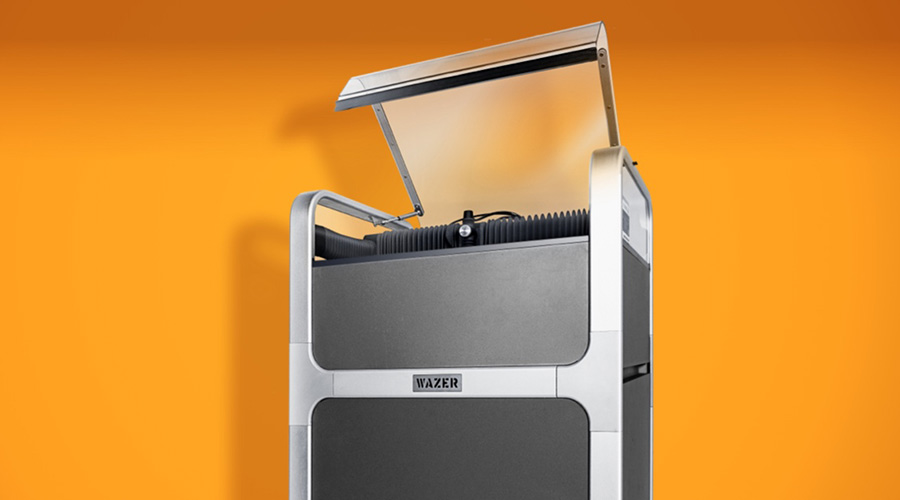
Why is WAZER the solution:
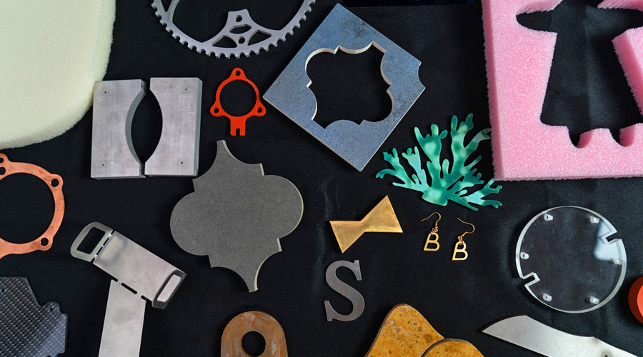
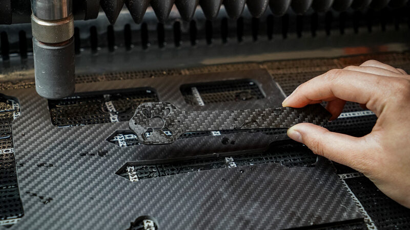
The WAZER waterjet can easily cut through a wide range of different materials. One of these materials is Carbon Fiber, which is known to be a very difficult material to cut with precision while leaving a clean edge finish. By using the WAZER for waterjet cutting carbon fiber, there is no need to outsource or overpay for predesigned parts. Furthermore, 4mm Carbon Fiber is often very difficult to machine using a CNC machine because of the number of passes required to cut the desired shape. The WAZER cuts down significantly on the cutting time since the design is cut in a single pass. Using WAZER, I was able to cut a completely new, multi-piece frame for my drone in less than a day from several thicknesses of Carbon Fiber.
How to cut Carbon Fiber with high accuracy
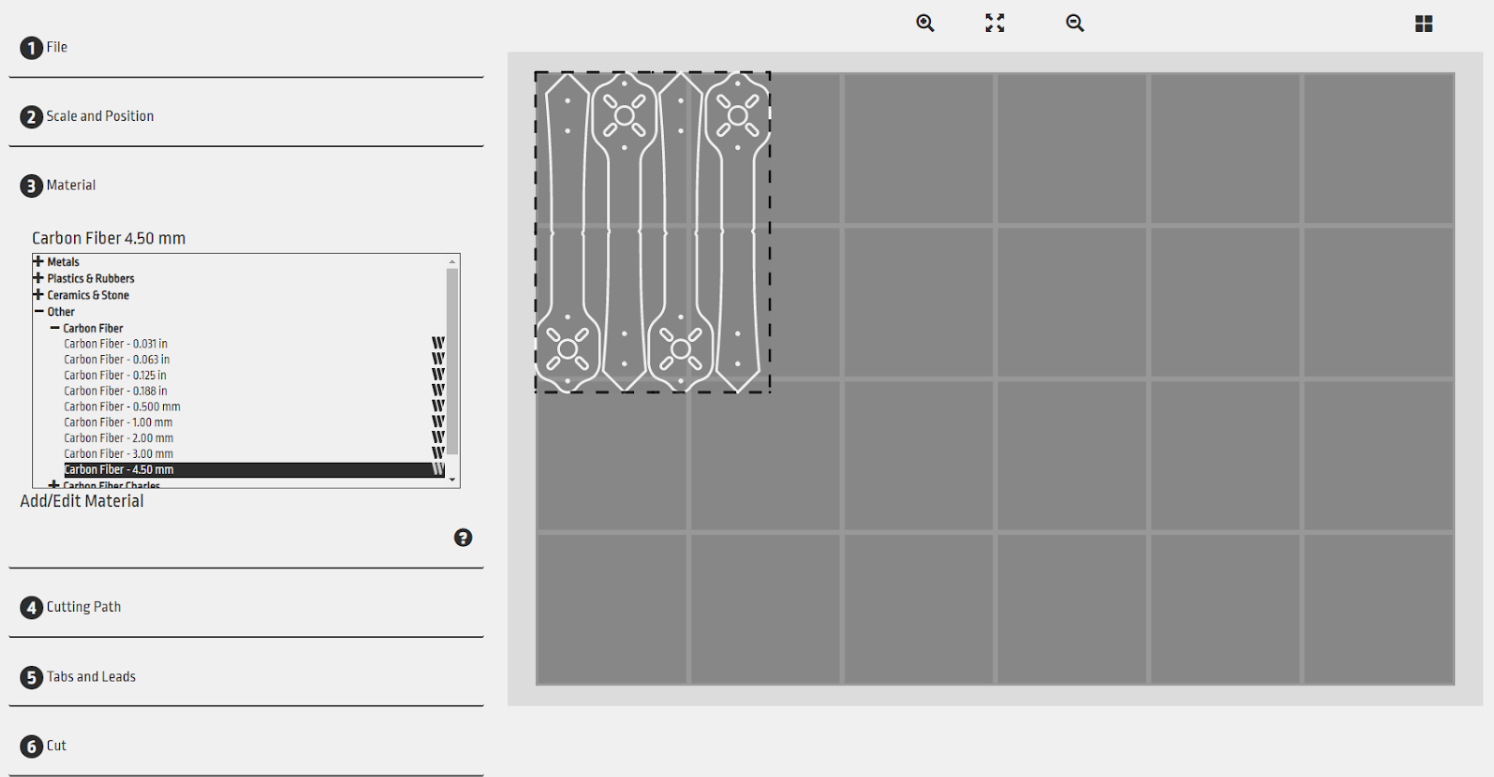
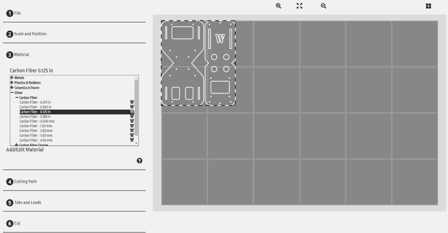
Designing a drone frame includes creating a lot of holes for mounting electronics or joining the pieces together. This requires cutting the Carbon Fiber very precisely. In order to avoid any issues when it came to the screw or bolt holes, I only marked the location of the holes rather than cut the actual holes to their final diameter. This is done through the CAD software I chose to use. By making the diameter of the holes the kerf size of the WAZER cutting stream, the WAM cutting software will translate that to a “pierce”, marking the exact location of the holes for post-process spot drilling later on. This ensured that the small holes needed for assembly were the proper final size, and had no issues with edge delamination, which would weaken the assembly.
Key Design Considerations
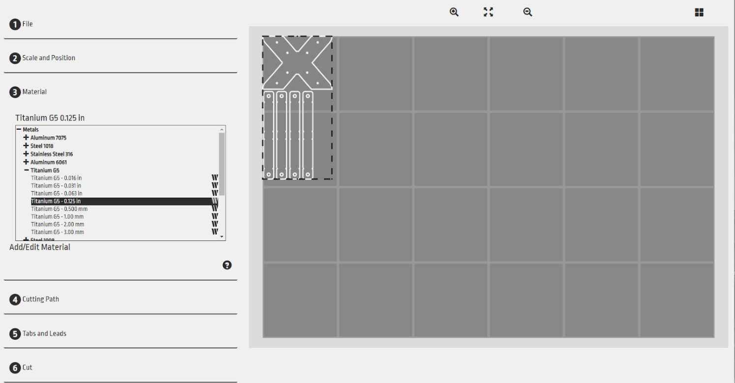
Generally speaking, quadcopter geometry is as follows: there need to be 4 nodes to which the motors will be mounted. The layout of those 4 mounting nodes may vary. As seen in the image below, quadcopters have five typical designs. In my design, I decided to design the quadcopter frame as a True-X since it is one of the most common node layouts used in commercial drone kits.
When it came to designing the frame, each component size was taken into consideration. It was important to know exactly where each component was going to be mounted in order to make the appropriate holes to screw parts onto the frame. Schematics for the motors, flight controller, battery, and PDB were key to determining the hole locations and distance so that the components could be properly secured for flight.
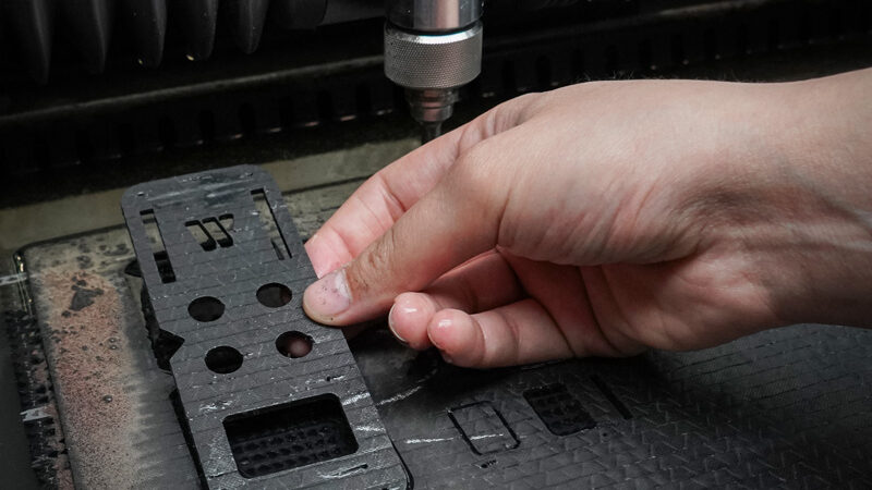
To maximize the usable area when cutting the Carbon Fiber sheet, the drone geometry was simplified by breaking down the “X” shape of the frame into several smaller pieces. The arms were modeled to be screwed into place on a base plate. The base plate is less thick than the arms and will be reinforced with titanium to ensure it won’t break in the event of a crash.
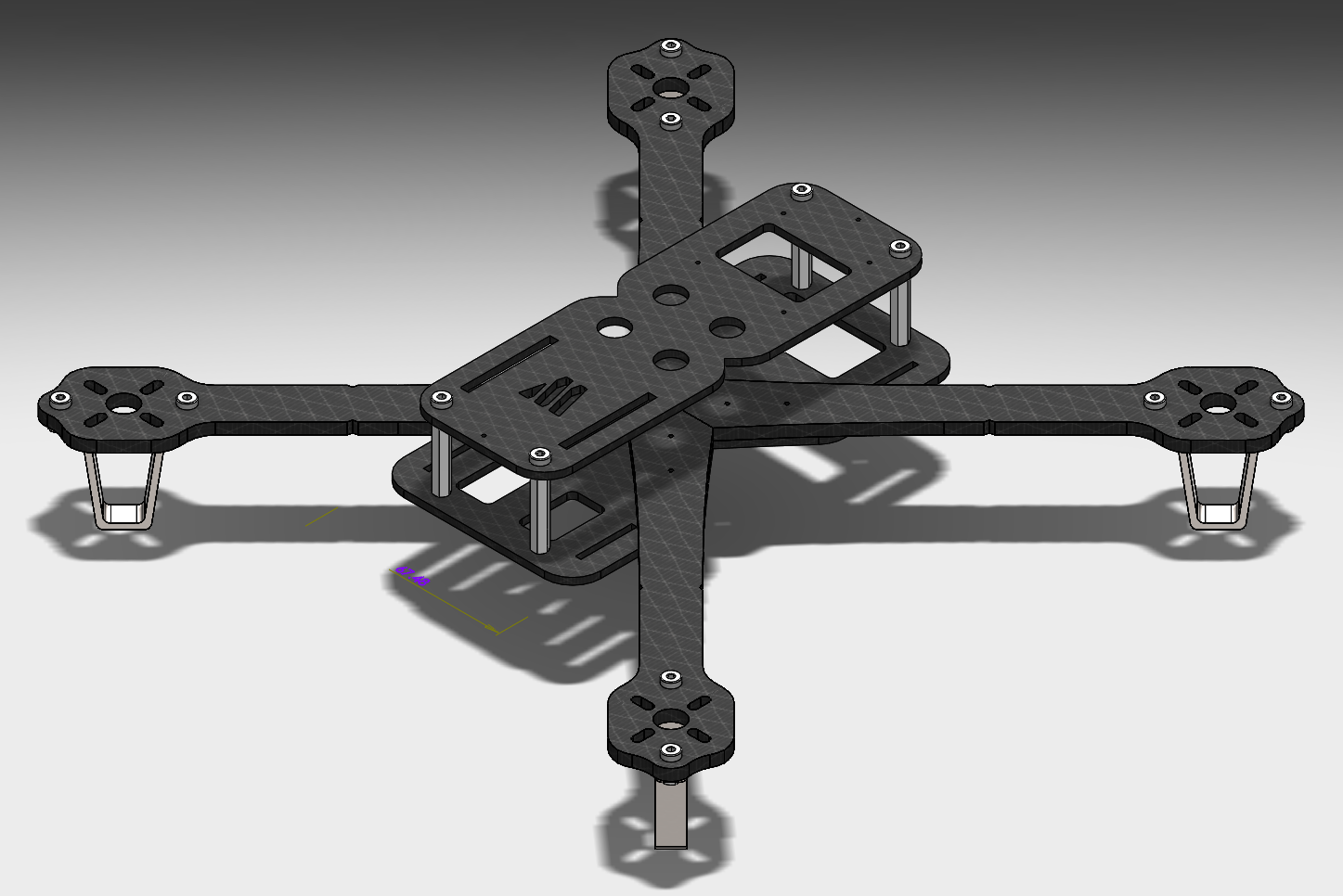
The Final Design
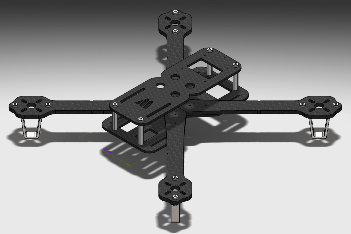
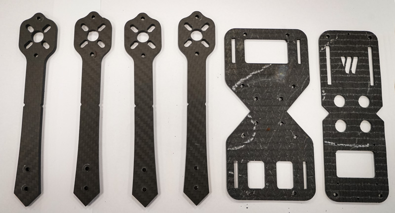
After looking at the individual parts and determining where each part would be placed, the design for the top and bottom Carbon Fiber plates were determined.
Cutting
I used two thicknesses of Carbon Fiber. I used 2.5mm Carbon Fiber for the top and bottom plate to reduce the overall weight. To reinforce the surface area of the bottom plate that is bolted to the arms, I cut a spacer from titanium on the WAZER which also lowered the center of gravity of the drone closer to the height of the motors. I used 4mm Carbon Fiber for the rotor arms since they are not very wide and tend to absorb the most force in a crash. Using some stainless steel, I cut out four landing feet for each drone arm.
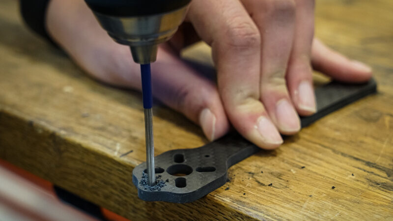
Post-processing and assembly
Most of the post-processing on the cut pieces was drilling out the various 3mm holes for the M3 bolts. Once all the holes were drilled, everything was assembled. Various lengths of M3 bolts were used depending on the thickness of Carbon Fiber being bolted. To space out the bottom and top plate, I used standard plastic standoffs, which can be easily replaced if anything were to happen to them.
To improve the surface finish of the Carbon Fiber pieces, I used a clear matte spray to create an even shine.
The basic frame without the titanium reinforcement weighed 117g. With the titanium reinforcement in place, it weighed 140g, which is well within the acceptable range that the motor blades I used can carry.
For wire management, zip ties are the light and easy way to secure any loose wires, and Velcro was used to secure the LiPo battery to the bottom of the drone.
Once the drone was completely assembled, I took it out on a calm day and enjoyed several hours of trouble-free flight. Even with the occasional rough landing and straying into the trees, it performed better than the commercially available alternative, and I was confident I could easily replace any damaged parts going forward.
I strongly encourage you to get out and make something unique to test your design and fabrication skills.