Overview
In my other tutorial, we explored the basic Sheet Metal features in Solidworks that help with bending sheet metal and making precision 3D designs. However, there is another method of creating 3D designs from sheet metal that might not be appropriate for bending.
Solidworks has introduced the “Tabs and Slots” feature in its most recent versions. This allows the user to create sheet metal designs and have Solidworks automatically create tabs where different sheets meet.
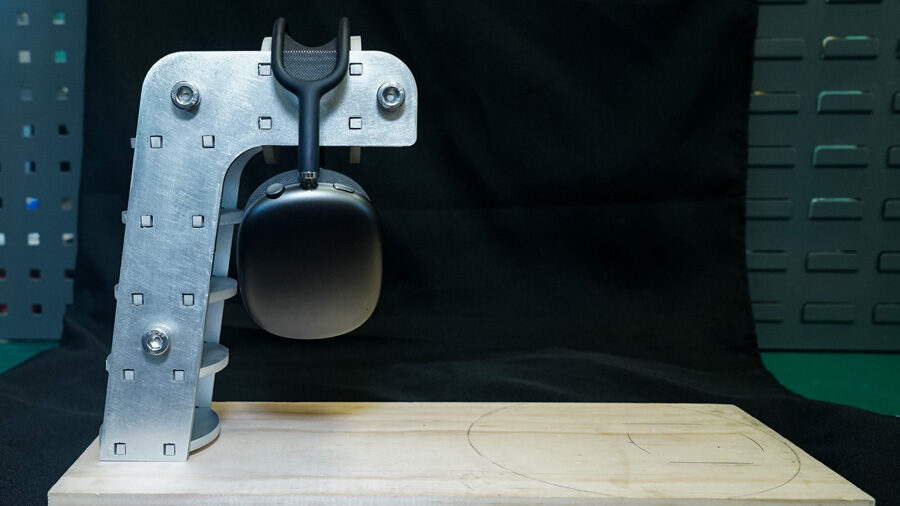
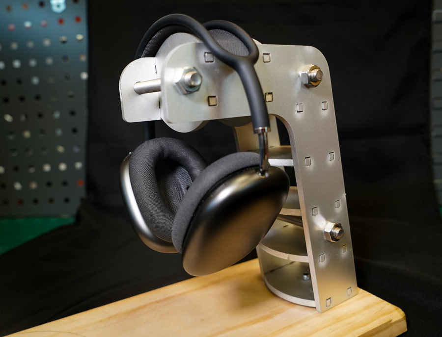
This tutorial contains cut files for a Sheet Metal headphone stand made from 0.23” aluminum plate. This step-by-step is provided to guide you through the Solidworks Sheet Metal Tabs and Slots feature and the cutting and assembly process for making this industrial-looking headphone stand.
Introduction
What is Solidworks Tabs Feature and how does it work? Solidworks introduced the Tabs and Slots feature in the Sheet Metal Tab in 2018. This feature allows the user to create an interlock between two adjoined sheets of metal. This feature saves the user a lot of time as the user does not need to manually figure spacing, tolerances, or tab patterns.
How does this feature work? It takes into consideration the material thickness and a standard tolerance, which can be adjusted depending on the manufacturing method. It can also adjust the width of the tabs and many more options to create the ideal tabs and respective slots
Designing the Headphone Stand
The design for the headphone stand was very basic. The key measurements here are the total height of the headphones and the thickness of the headband. This was important in order to determine how high the stand would sit and how big the gap needed to be between the center metal pieces
. All the measurements were translated into a Solidworks Sheet Metal Design as seen below.

How to put Tabs and Slots in Solidworks
- First, select the Tabs and Slots feature in the Sheet Metal Tab.
- It will first prompt you to select the Tab Edge.

- Then it will prompt you to select a Slot face which needs to be the outermost face from the Tab Edge. The rest of the inputs should be automatically selected by the software itself.

- You can select the appropriate number of tabs and the desired spacing option of either Equal Spacing or Spacing length. For this tutorial, Equal spacing was the optimal spacing option.

- You can also adjust the Tab Length, thickness, height, and edge type.
- Finally, you have the option to select a slot offset for the height and width of the slot. This plays an important role when machining your piece because you want to make sure that the tabs and slots interlock well enough to hold your design together.
- You can repeat the above process as many times as needed so that all your separate metal parts have tabs and slots.
- Once you have completed the tabs and slots, click to save each face as a DXF to be able to upload to WAM and cut out.
WAM Setup
- For this design, a centerline will be used to account for the tolerance associated with the width of the tabs and slots. As for the tolerance associated with the height of the tabs and slots, the centerline also takes care of that in the two side pieces. There is an offset of 0.022 inches with the centerline cup path. For the middle pieces, the tolerance was accounted for in the material thickness.
- Setup for the Headphone stand
- To get started with WAM, firstly import FirstHalf.DXF and position the design on the top left corner of the cutting area.
- Then, to select the material, in the pre-existing database for materials, we will select Metals → Aluminum 6061→ and a thickness of 0.25 inches.
- For the cutting path, choose a centerline cut path with one tab for each piece with a size of 0.001 inches.
- For the cut quality, choose a medium-quality cut for a good finish with minimal chipping on the edges.
- Download G-CODE.
- Repeat the setup for the SecondHalf.DXF.
- Load both files onto an SD card.
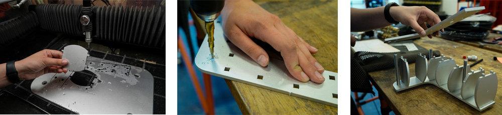
Post-Processing
- Using a file, remove the tabs from each piece to ensure a smooth fit.
- Spot drill the 10mm holes out for the M10 bolts.
- Assemble the stand using the M10 bolts to secure the whole thing together.
- For the base, use a Dremel motor tool to make the two channels for the base of the assembly to be inserted into and drill the 10mm hole for the bolts that will attach the stand to the base.
Conclusion
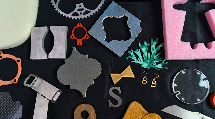
There you have it. After my 2 most recent tutorials, you should be ready to take on any sheetmetal challenges that await you and your business. The true power of the small waterjet is its versatility, and the ability to be used in a wide variety of manufacturing applications without the need for expensive tooling or complicated material setups. How would you harness all that power in your business?