Overview
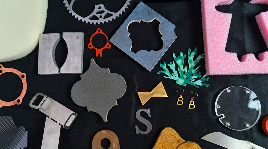
Sheet metal is a versatile material that can be used to make many things, from industrial components, to electronics enclosures and even creating simple toys. However, the material can be tricky to work with, and traditional CNC methods have varying degrees of success cutting multiples of it accurately without significant tooling costs. Waterjet cutting sheetmetal on a machine like the WAZER is an excellent way to maintain precision while keeping the work in-house.
Solidworks is an excellent tool for taking your ideas and visualizing them with CAD. It also has a very useful built-in tool set for sheet metal designs. In this tutorial, we will learn and explore the capabilities of the Sheet Metal tools in Solidworks so we can bring our sheet metal project to life. If you’re new to the program, or want to follow along, you can also refer to their excellent help files.
Introduction
What are the Sheet Metal Tools in Solidworks, and how do we convert a Solid Body to a Sheet Metal? Aside from the Features and Sketch tabs which are the welcome tabs most people are familiar with, there is a Sheet Metal tab that contains all the tools necessary for sheet metal design. This tutorial will explore how you can take your solid body design and convert it into a sheet metal that folds and unfolds. This is especially useful when you have already designed a solid body design and you want to change the manufacturing method used.
Converting a Solid Body to a Sheet Metal Box
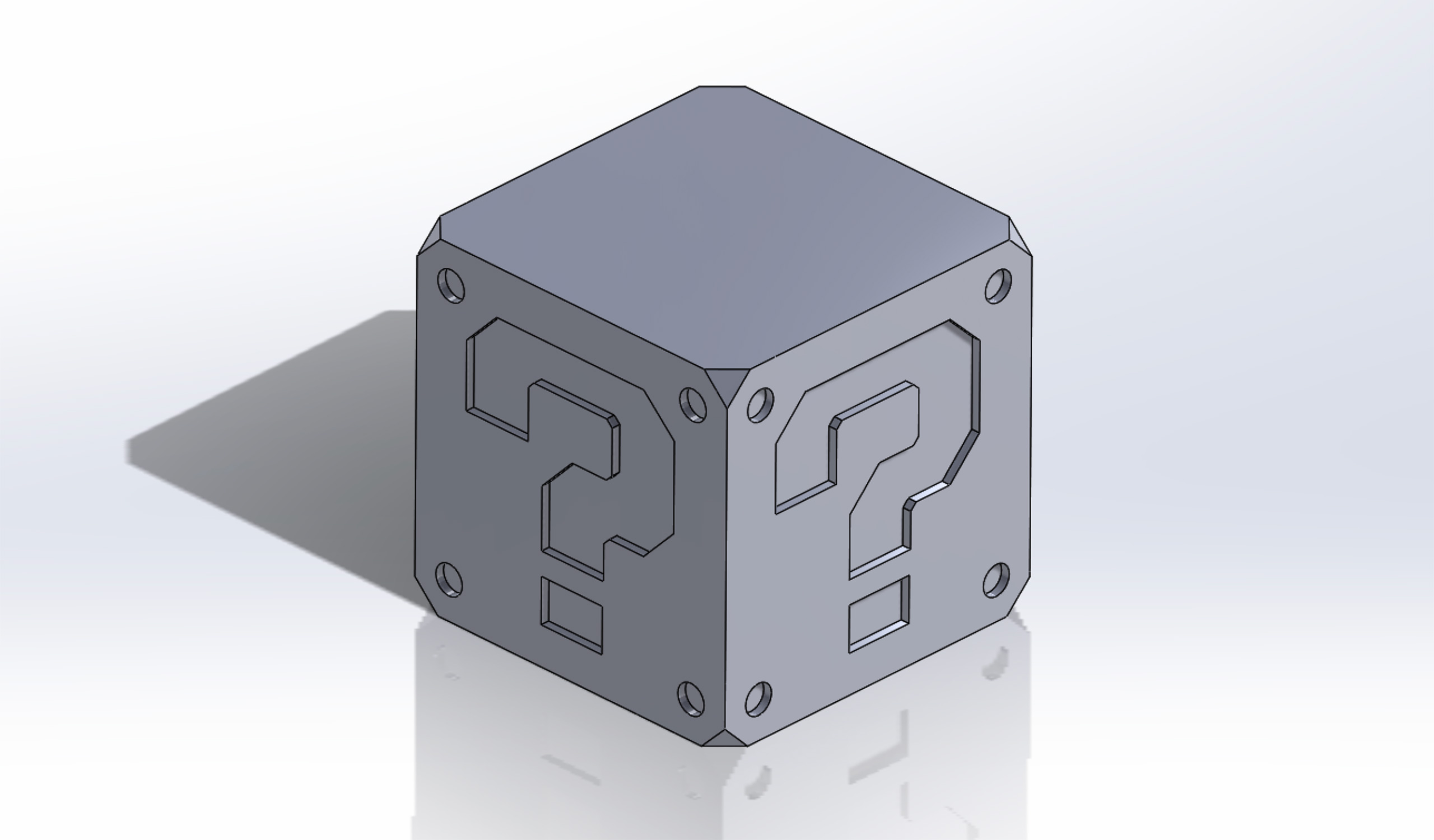
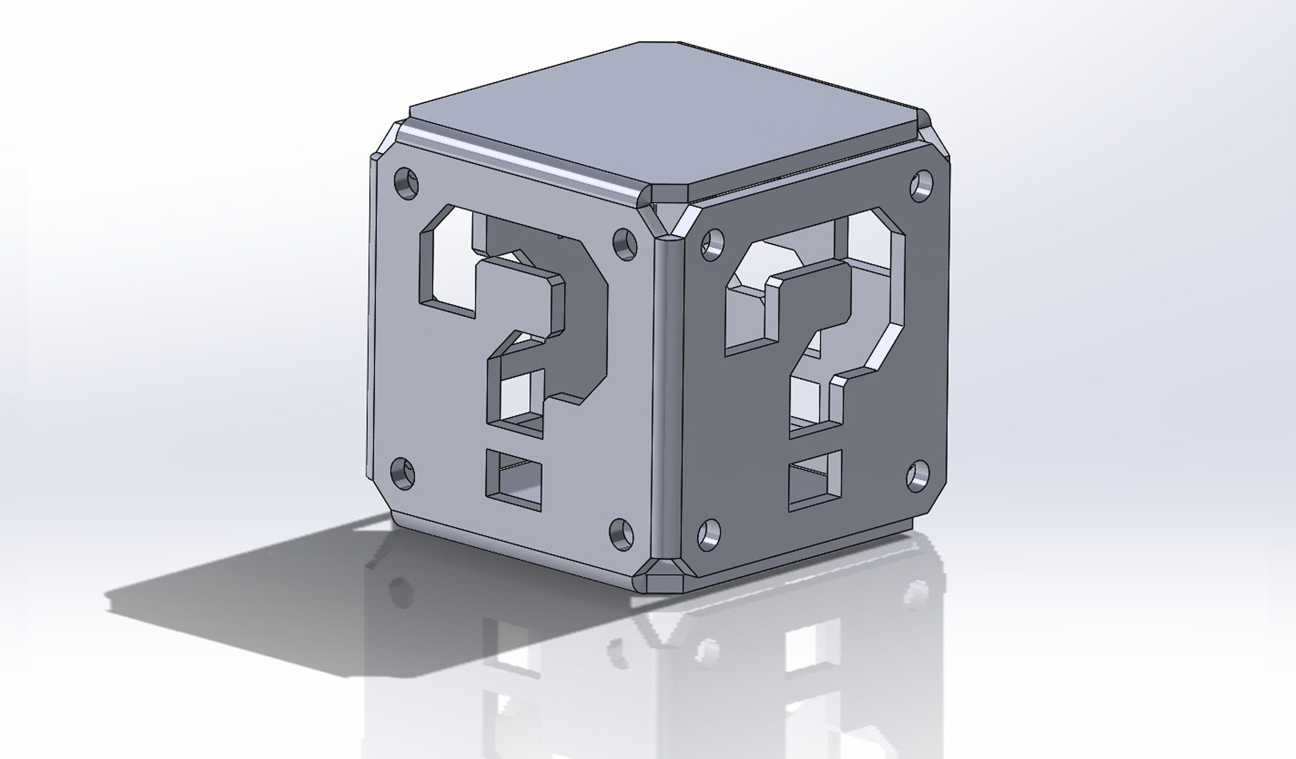
In this part of the tutorial, we will look at a Solidworks tool that comes in handy when you have designed something in the software as a solid body but wish to make the design from sheet metal. A good example is this question mark box which is constructed as a solid body. It has designs on each surface which we wish to maintain for a sheet metal design.
Solidworks Steps
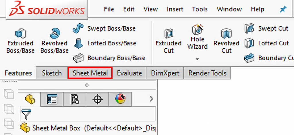
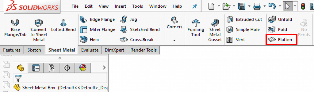
- Let’s begin by locating the Sheet Metal tab on the toolbar. If you can’t find it, left-click on the toolbar and add the Sheet Metal tab to the toolbar.
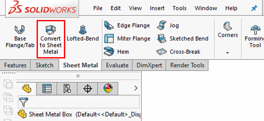
- Click on the Sheet Metal tab and find the Convert to Sheet Metal button.
- First, input the thickness of the material.
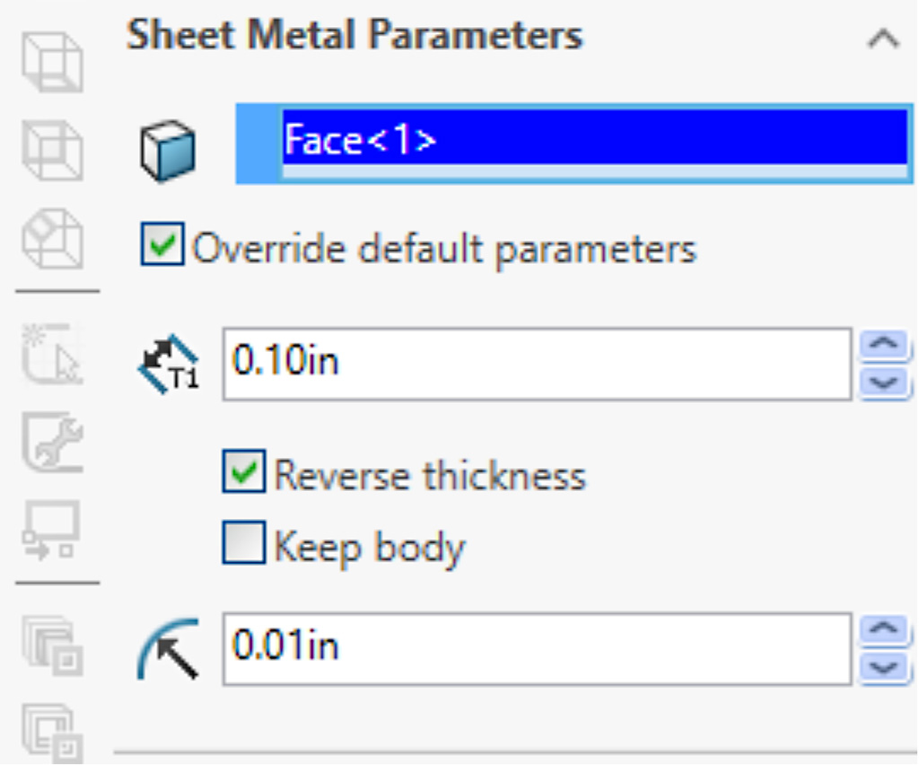
- The property manager for the Convert to Sheet Metal should open up and prompt you to select a fixed entity. Select one of the cubes faces with the question mark.
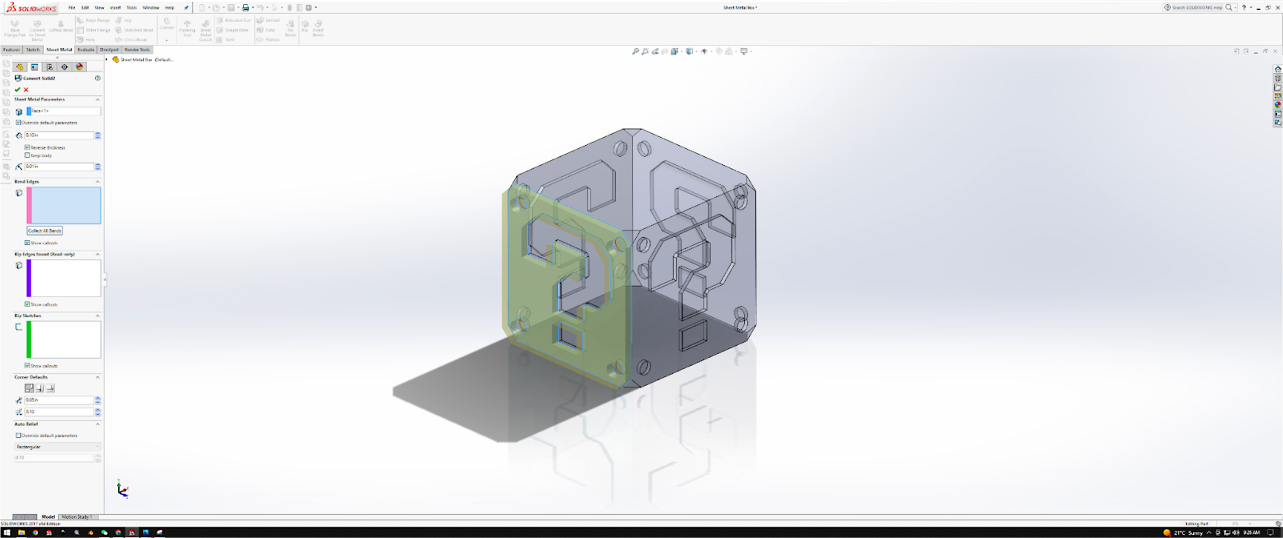
- Then, Solidworks will need to know what edges to bend. In order to do that, simply select the adjacent edges to the Fixed Entity face. Notice the edges will turn pink, indicating the Bend Edges, and purple indicating the Rip Edges.
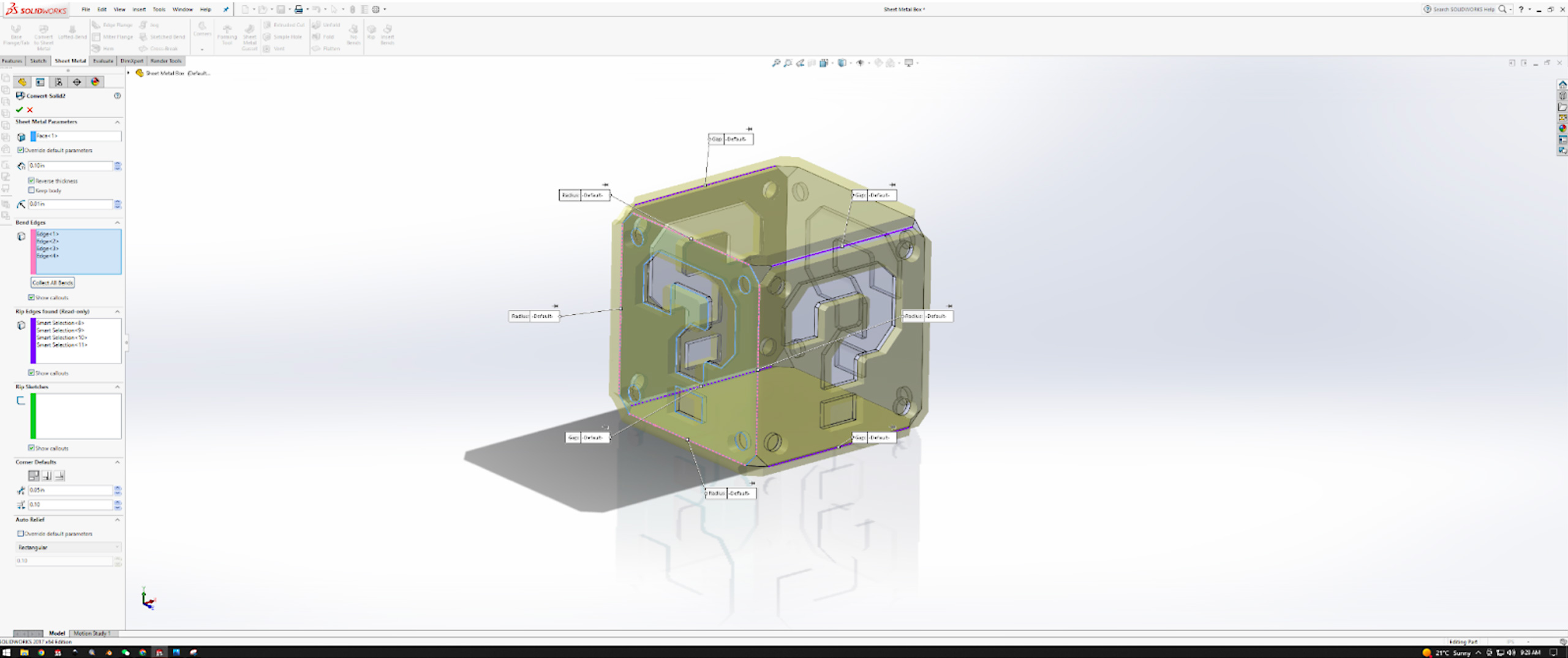
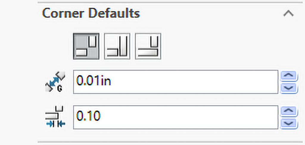
- Repeat the above step until all faces are highlighted yellow and each edge has either been defined as a Bend Edge or Rip Edge. Before confirming the Convert to Sheet Metal, change the distance between the faces for the Rip Edges. This is done by going into the Corner Defaults and changing the Default Gap for All Rips.
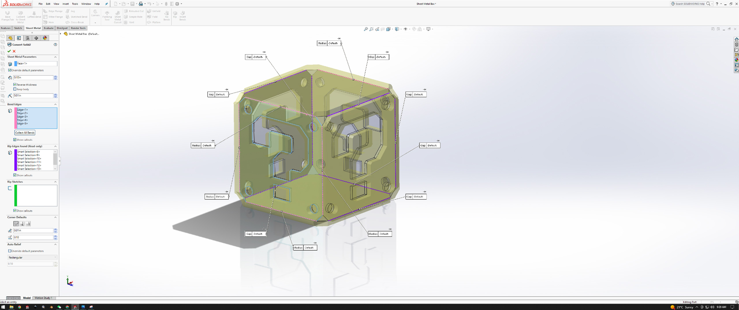
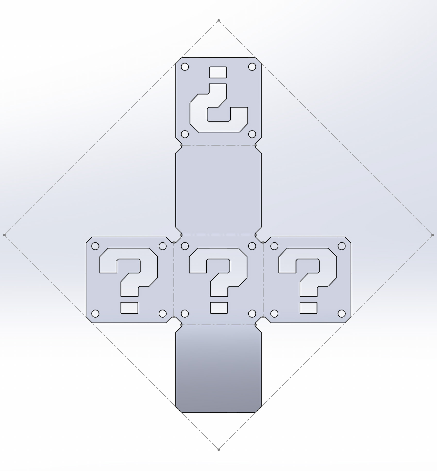
- Once you confirm the Convert to Sheet Metal, you should be left with the folded sheet metal question box.
- You can view the flat Sheet Metal design by clicking the Flatten tool on the Sheet Metal Tab.
- In order to help with the sheet metal bending after the cut, we will add bend relief cuts. Simply create a sketch on the flattened design and draw straight slots on the edges being bent.
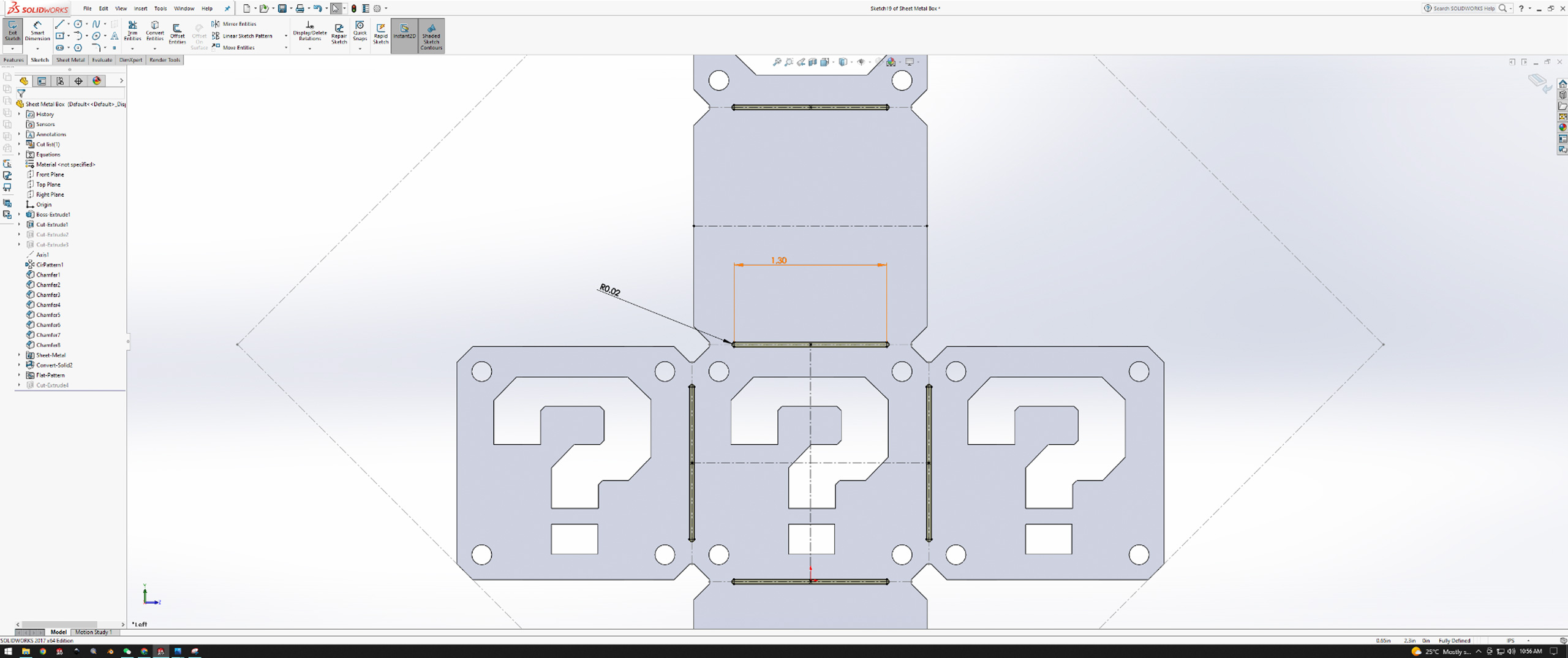
- Extrude cut the slots to create gaps in the sheet metal. This will help with the bending process.
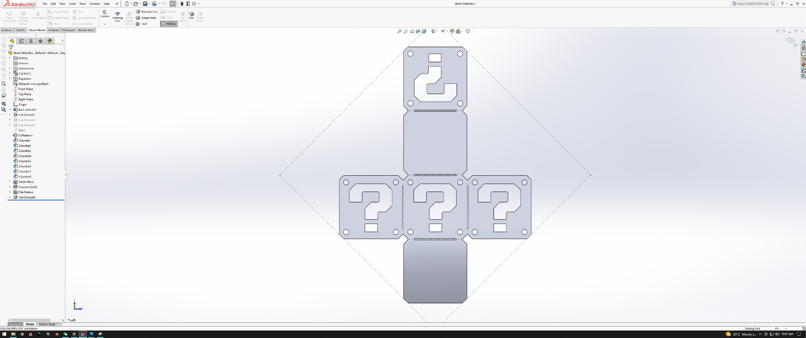
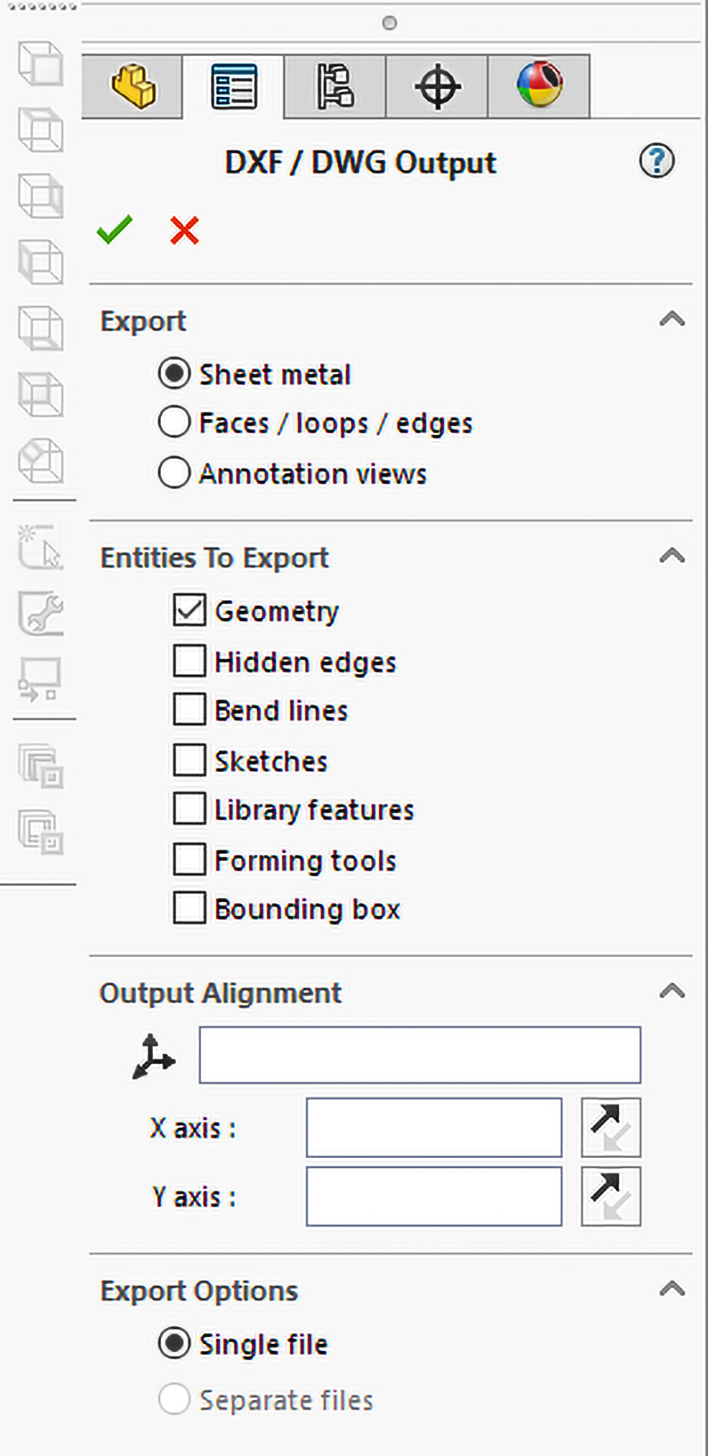
- Finally, left-click on the sheet metal and select to export the design as a DXF which will be imported to WAM to prepare for the cut. Make sure to select only the Geometry of the sheet metal to be exported.
Getting Ready to Cut
WAM Setup
- Import the DXF file for the box into WAM.
- Setup the file
- To get started, position the box net on the top left corner of the cutting area.
- Then, select the material in the pre-existing database for materials. We will select Metals → Aluminum → and a thickness of 0.1 inches.
- For the cutting path, choose a centerline cut path.
- Add tabs to the larger pieces to prevent the cutouts from getting stuck between the nozzle and the material.
- For the cut quality, choose a “fine” cut to avoid excessive post-processing.
- Download the resulting G-CODE
- Copy the cut file onto an SD card.
Setting up the cut on the machine
- Insert SD card into WAZER.
- Initialize the cut for the frame by following the instructions on the UI screen.
- Origin setup
- Fill abrasive hopper and empty used abrasive collectors.
- Level nozzle with respect to the material using the nozzle height tool.
- Start the cutting process.
Post-Processing
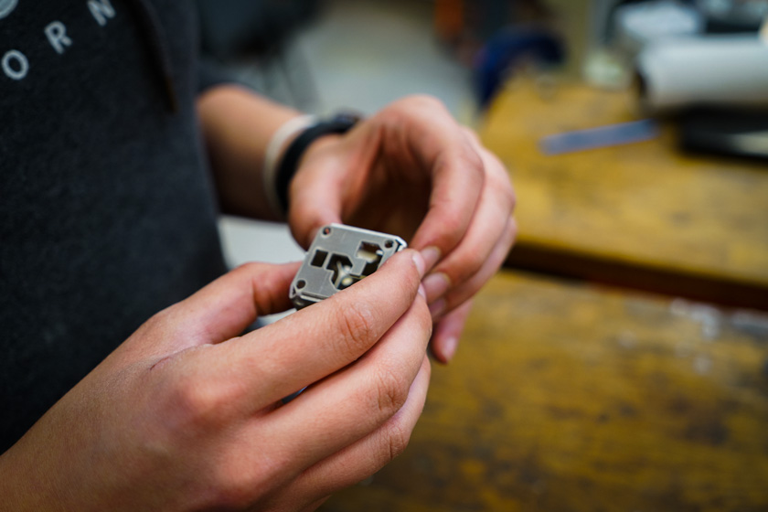
Waterjet cutting sheetmetal produces a nearly ready-to-use result. Once the design is cut, there are only a few quick and easy steps that need to be taken to make the piece ready for the assembly process and its end-use.
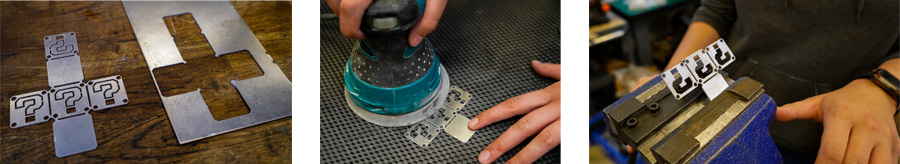
- Remove the cut piece from the rest of the material.
- File down the tabs.
- Using an orbit sander, sand down both sides of the cut sheet for a uniform finish.
- Using a hand seamer, vise, or pliers, bend the sheet into a cube.
Conclusion
The project is now complete. While I made a simple decorative Mario Cube, it could have just as easily been a precision electronics enclosure or some other “real world” use case. I find the most effective method to learn new techniques is to make the project fun and interesting, and give me a visual reminder I can refer back to as needed. What could you do with a custom cut sheetmetal enclosure?