Form Follows Function
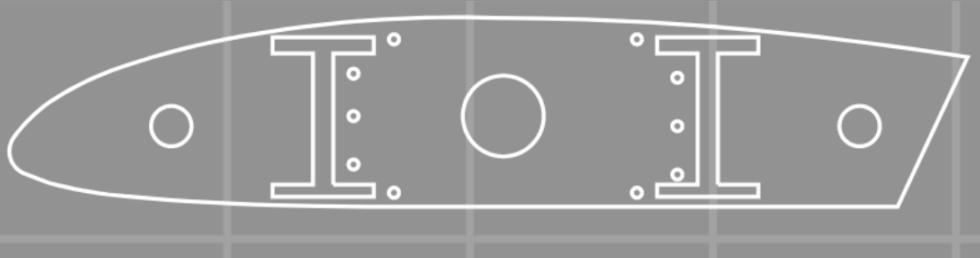
The WAZER can create highly accurate parts which can then become functional components. But what factors correlate with producing accurate parts? How can I work within the mechanical limits of the WAZER to perform high accuracy cutting? By better understanding the actual waterjet cutting process, you can consistently achieve accurate parts. To demonstrate, I chose a part that requires high accuracy: aircraft wing ribs. The specific design is the well-known Clark Y airfoil.
Wing ribs vary in shape and size depending on their intended use case, but a common factor is always the accuracy of the rib. Since these components experience high forces and need to be as lightweight as possible, it’s important that features are manufactured correctly to prevent component failures.
Cutting Accurately
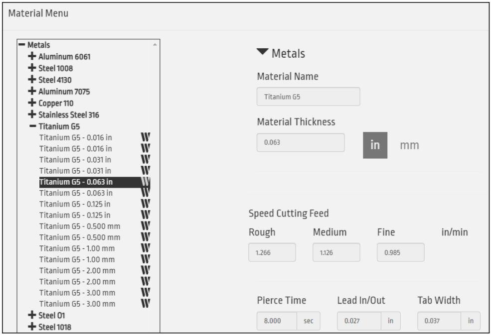
Important Factors of Waterjet Cutting : Water mixed with abrasive physically cutting the part is a constant, but how the WAZER cuts can vary based on the material, thickness, and the cut rate selected. All of these factors begin with an easy question: what material to use? Here, I chose titanium due to its low weight and its known difficulty to machine. The initial step was uploading the DXF design file into WAM, positioning it on the cut bed, and choosing the thickness of Titanium to cut. This allows WAM to use the information that comes preloaded in the material database, such as cutting speeds, tab size, and pierce time, as shown below.
The Ins and Out of Cutting Paths
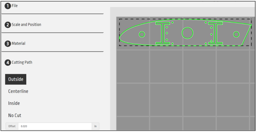
After placing the part and selecting the material, you then choose the cutting path that best fits the part. There are three options: Outside, Centerline, and Inside. Each one will affect the final dimension of the part. An outside cut offsets the waterjet stream (kerf) to one side of the white design line that will give the most accurate cut profile to the designed dimension.
The two other options, Centerline and Inside, move the jet stream to the center and inside of the design white line. This will cause the cut part to be smaller than the designed dimension, meaning that our best choice for accuracy is the outside cut path.
The next variable to take into account is the offset. The offset refers to the width of the kerf which is the nozzle width. WAM automatically sets this to 0.019 inch as this is the size of the nozzle. Extended use of the WAZER can lead to the nozzle opening increasing so I physically measured the actual width on the WAZER and found the nozzle was still at the original offset size.
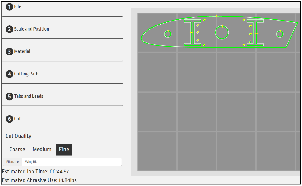
The last option in WAM that will help achieve higher accuracy is the cut quality. The three options range from a coarse to a fine cut quality. A coarse cut will be faster but result in a lower quality, while a fine cut will cut slower and produce a higher quality cut. Since I am aiming for high accuracy, I chose the fine setting.
Creating the Parts
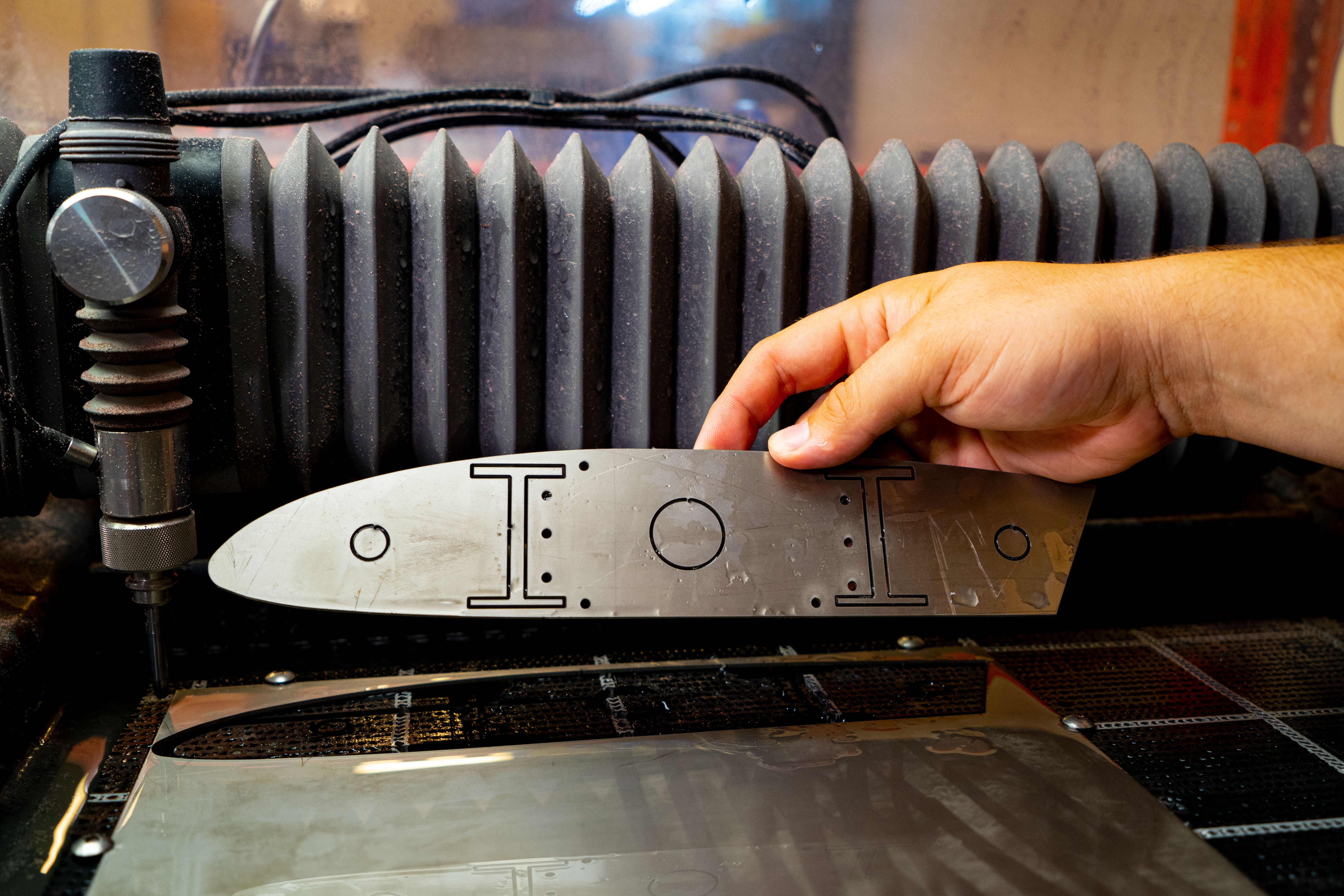
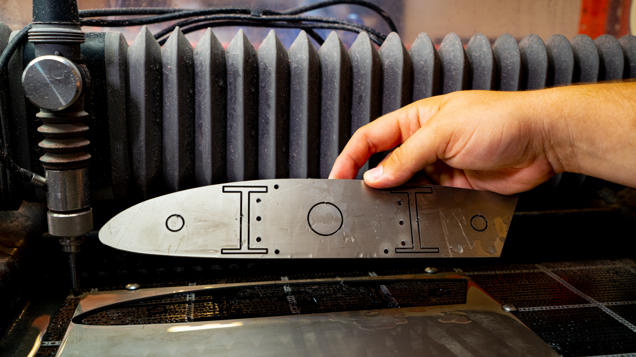
We can now generate the job file and move the WAZER cutting head into position so the design would span the entire sheet of material.
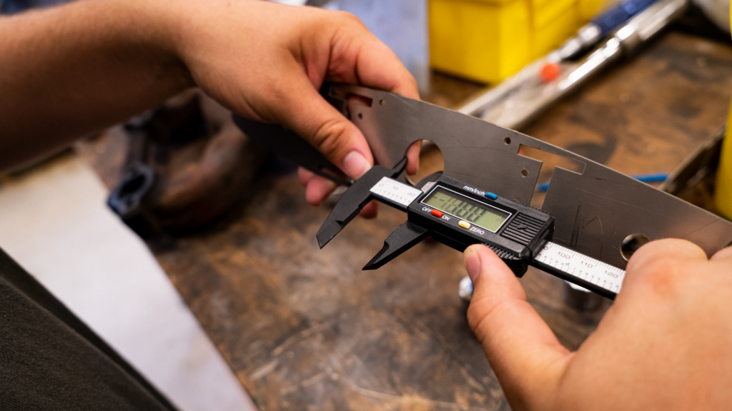
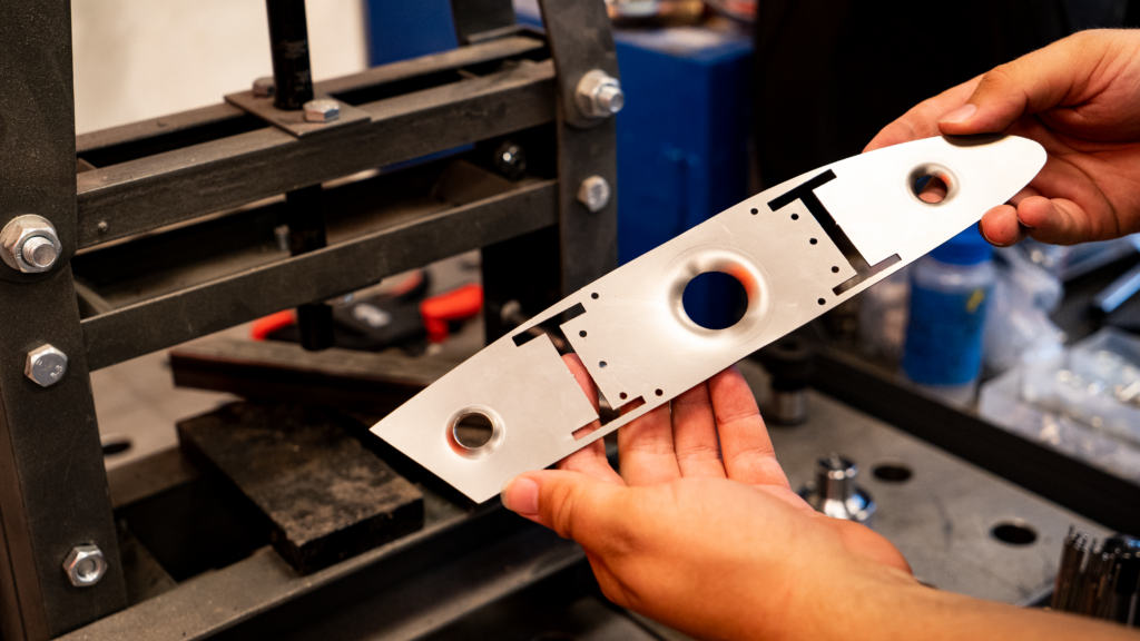
Once the cut was completed, I measured several points on the part to compare the physical part results to the design dimensions. Waterjet cutting titanium yielded excellent results without the need for expensive tooling or highly skilled technicians.
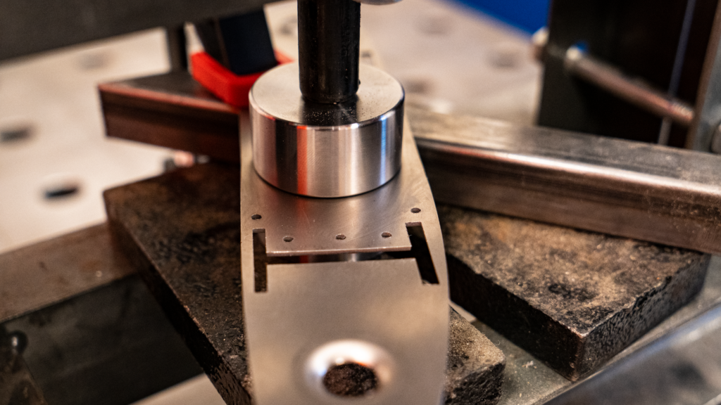
In an additional post-processing operation, I used a dimple die to get the classic curved circular cutouts that are on many aircraft components. These help increase the stiffness of the parts without increasing the weight. I’m quite pleased how this project turned out, and think there are many real-world use cases for this very process.