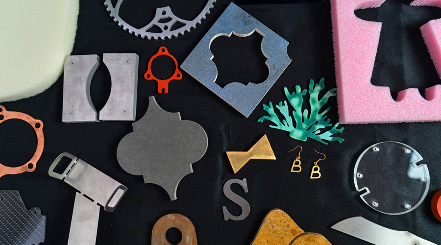
Sheet metal is a material you can make almost anything with, from industrial components, to machinery enclosures, household tools, or even a simple cup holder. The possibilities are endless.
Solidworks is a great tool for taking ideas and visualizing them in CAD. It also has a very handy built-in tool for sheet metal design. Here, we will learn and explore the capabilities of the sheet metal tools in Solidworks and how to use it to bring sheet metal projects to life using the WAZER waterjet.
This tutorial contains cut files for a sheet metal cup holder. A step-by-step guide is provided to guide us through the two methods of sheet metal design in Solidworks. This article also explains my process for setting up and cutting the parts on the WAZER CNC waterjet cutter.
TOOLS NEEDED
- Orbital sander
- Files
- Sandpaper
- 3M x 10 Screws and nuts
INTRODUCTION
How do we make a sheet metal design from scratch?
It may be straightforward to convert a solid body into a sheet metal design, but how do we tackle a sheet metal design from scratch? Solidworks has a tool set that allows you to make flanges and base flanges without having to open up sketches each time.
Making a Sheet Metal design – Cup Holder
Having looked at one of the ways in which we can make a sheet metal design, what if we wanted to make a sheet metal design from scratch? In this part of the tutorial, we will explore some more of the Solidworks sheet metal tools by making an adjustable metal cup holder for your lawn chair.

Steps
- Begin by creating a new part file in Solidworks. Then, locate the Sheet metal tab in the toolbar.

- Then click on the Base Flange/Tab tool which will prompt you to select a sketch plane. Choose the top plane. The sketching process for Sheet Metal is exactly the same as the sketching process for a solid body. Replicate the sketch below.

- After the sketch is completed, it will ask you for the Sheet Metal parameters. Enter the thickness of your sheet metal. For this tutorial we are using 0.14 inch thick Aluminum.

- Once the base has been made, click on the Edge Flange tool. This tool will allow us to create an edge flange from existing edges on the base flange. Let’s create the flange on the left side. Select the top edge of the left side and create a flange with an angle of extrusion of 90 degrees and a distance of 2.35 inches.

- Using the same tool, create a flange on the right top edge of the base flange with an angle of 80 degrees and a length of 2.55 inches.

- On the left side create a flange from the outer edge of the existing flange with an angle of 90 degrees and a length of 0.1 inches.

- On the top face of the flange just created, create a drawing using the dimensions below and extrude the sketch according to the width of the material used which in our case is 0.14 inches.

- On the right side, create a flange on the existing flange by selecting the inner edge. Create a flange with an angle of 100 degrees and a length of 0.3 inches.

- On the face of the flange just created, make a sketch as shown in the image below. Ensure the circles in the sketch are concentric with the circles on the base flange. Extrude the sketch according to the material thickness.

- Create a flange from the bottom edge of the new geometry. Extrude the flange at a 90-degree angle with a length of 0.80 inches.

- Once all the design has been completed, add fillets to the sharp corners for aesthetics.

- Add two 3mm holes to the

- Create a sketch on the top face of the design and add two straight slots.

- Create another sketch on the outer vertical face as seen in the image below.

- Finally, add another slot to the inner vertical face as seen in the image below.

- You can now press the Flatten tool to see the flat sheet metal design. This is what WAZER will cut out.

- To help with bending the sheet metal after the cut, add relief cuts that will also help indicate where the bending needs to happen.

- We need to make two grip pieces using the same tools to create the flanges.


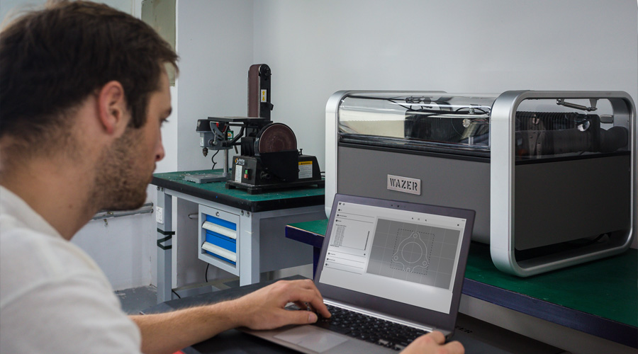
WAM Setup
- Import the DXF file for the box into WAM
- Setup for the file
- To get started, position the box net on the top left corner of the cutting area.
- Then, select the material in the pre-existing database for materials. We will select Metals → Aluminum → and a thickness of 0.125 inches.
- For the cutting path, choose a centerline cut path.
- Add tabs to big pieces to prevent the cutouts from getting stuck between the nozzle and the material.
- For the cut quality, choose a fine cut to avoid rigorous post-processing.
- Download G-CODE
- Load the file onto an SD card.
Setting up the cut on the machine
- Insert SD card into WAZER.
- Initialize the cut for the frame by following the instructions on the UI screen.
- Origin setup
- Fill abrasive hopper and empty used abrasive collectors.
- Level nozzle with respect to the material using the nozzle height tool.
- Start the cutting process.
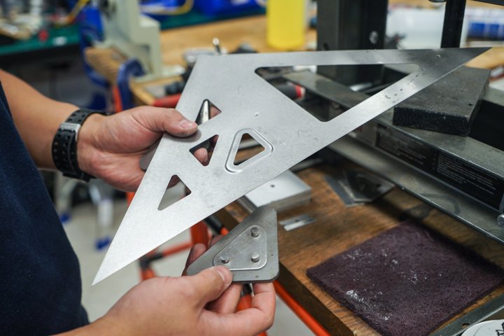
Post-Processing
- Remove the cut from the rest of the material
- File down the tabs
- Using an orbit sander, sand down both sides of the cube net for a uniform finish
- Using a vice or pliers, bend the cup holder and grip pieces into the appropriate shapes.
Conclusion
This is an enjoyable project that can help you better understand the tools built into Solidworks, and a practical exercise is always the one that is remembered best.